A comparative study of ptdf based - Methods to determine transmission usage allocation for bilateral transactions in power markets
Ngành điện đã và đang tái cấu trúc với mục đích tạo ra sự cạnh tranh
giữa những người tham gia thị trường điện. Sự tái cấu trúc này dẫn
đến những khó khăn đáng kể cho các đơn vị vận hành hệ thống điện.
Một trong những khó khăn này là các đơn vị vận hành hệ thống điện
cần cung cấp cho đơn vị tham gia thị trường quyền sử dụng lưới điện
truyền tải một cách công bằng. Trong nghiên cứu này, phân bố công
suất trên lưới điện truyền tải của các giao dịch song phương được
phân tích và so sánh sử dụng hệ số phân bố truyền tải công suất
(PTDF). Hệ số phân bố truyền tải công suất được phân loại thành
DCPTDF và ACPTDF. Kết quả tính toán từ cả hai tiếp cận này sử
dụng các hệ thống điện 3 nút và 6 nút Wood & Wollenberg được
phân tích và so sánh. Sự so sánh cho thấy phân bổ công suất trên lưới
truyền tải của các giao dịch song phương khi áp dụng hệ số ACPTDF
chính xác hơn nhưng phức tạp hơn so với sử dụng hệ số DCPTDF.
Kết quả nghiên cứu trong bài báo này cung cấp sự đánh giá chi tiết để
hỗ trợ các đơn vị vận hành hệ thống điện đạt được sự công bằng
trong hoạt động thị trường điện.
Trang 1
Trang 2
Trang 3
Trang 4

Trang 5
Trang 6
Trang 7
Trang 8
Tóm tắt nội dung tài liệu: A comparative study of ptdf based - Methods to determine transmission usage allocation for bilateral transactions in power markets
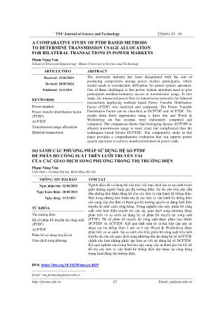
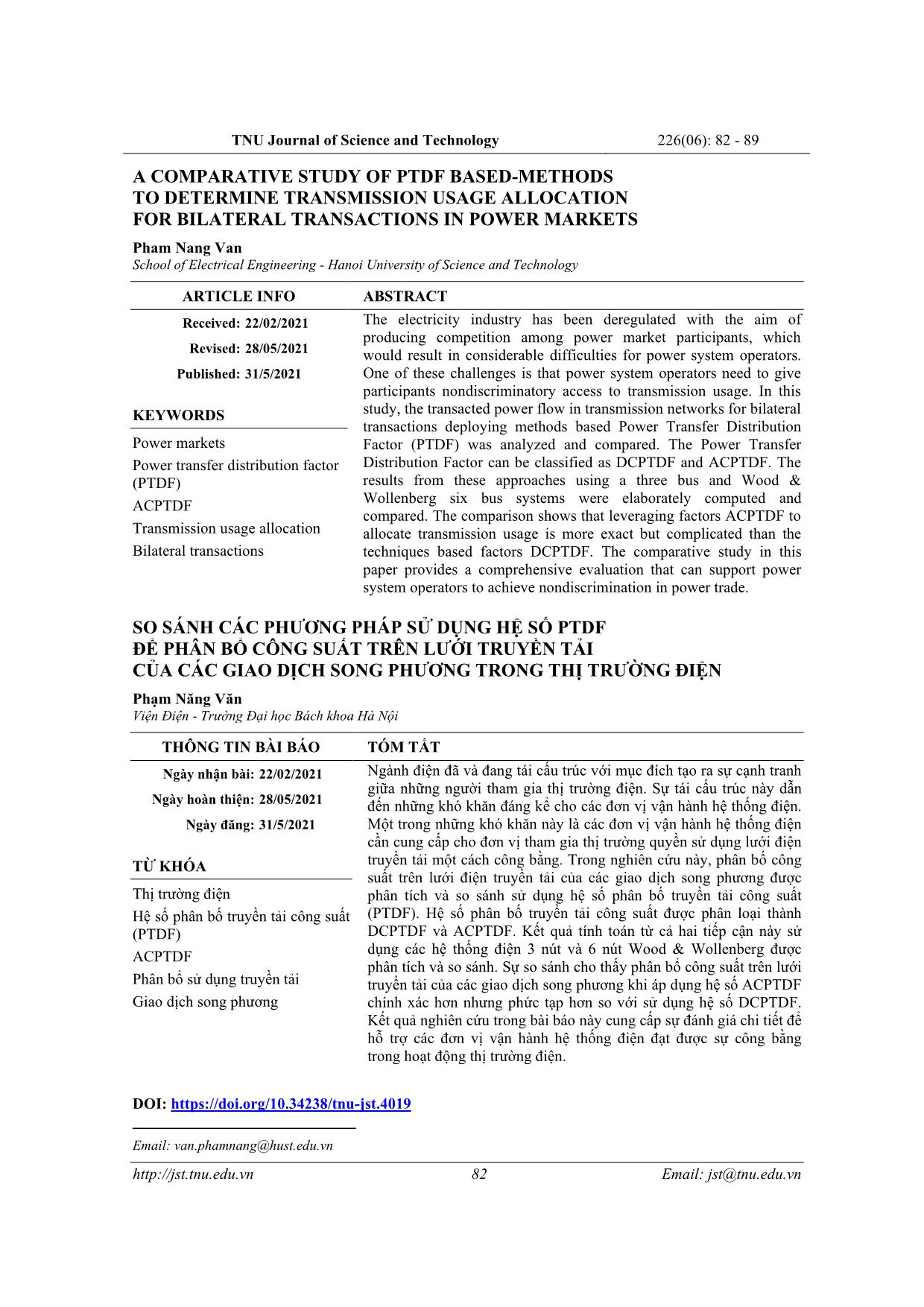
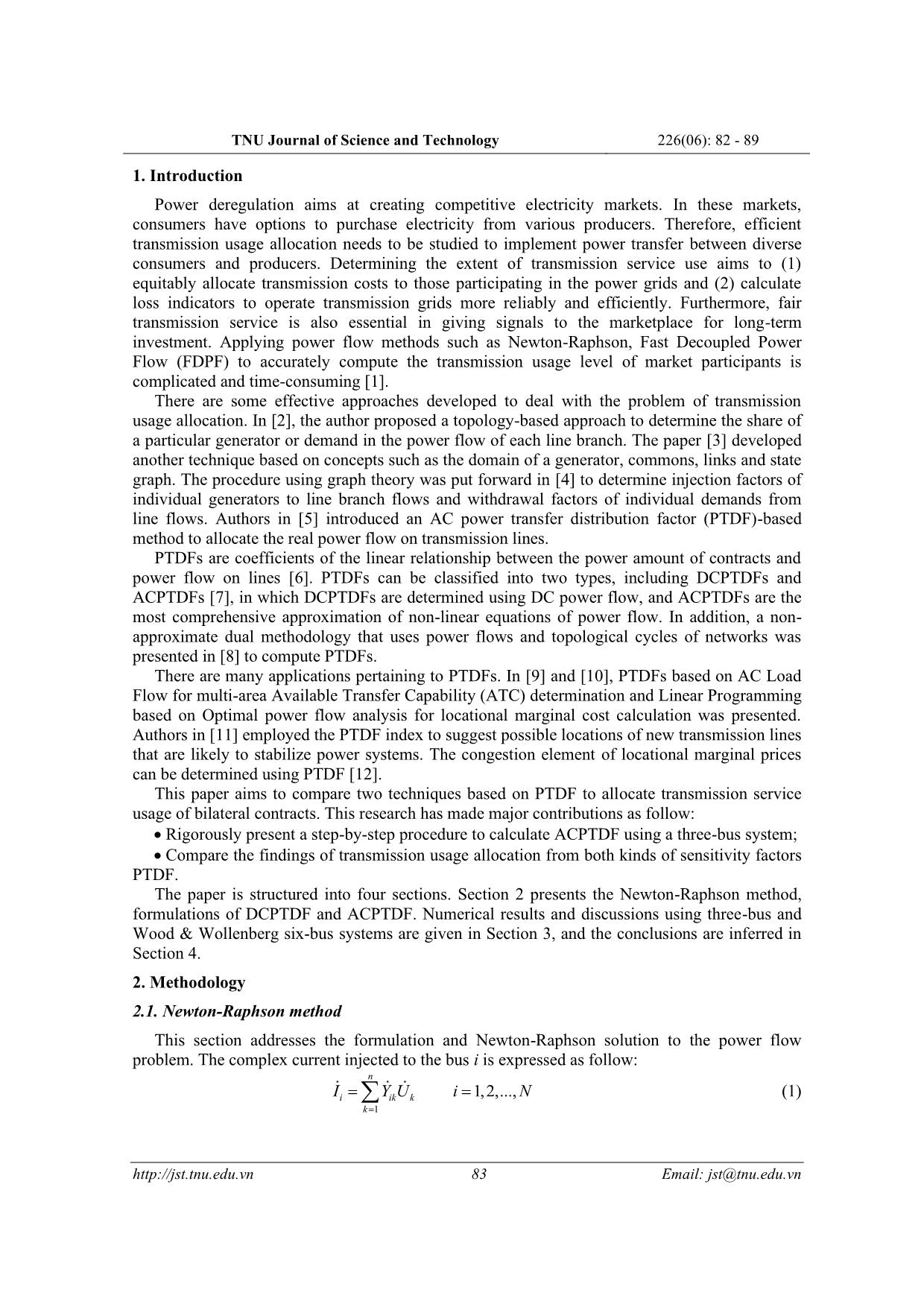
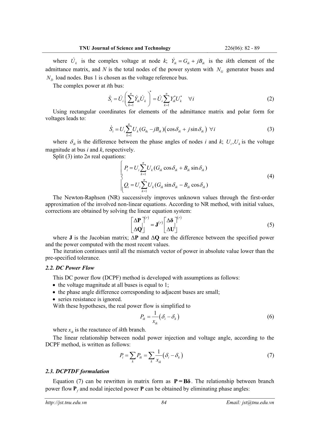
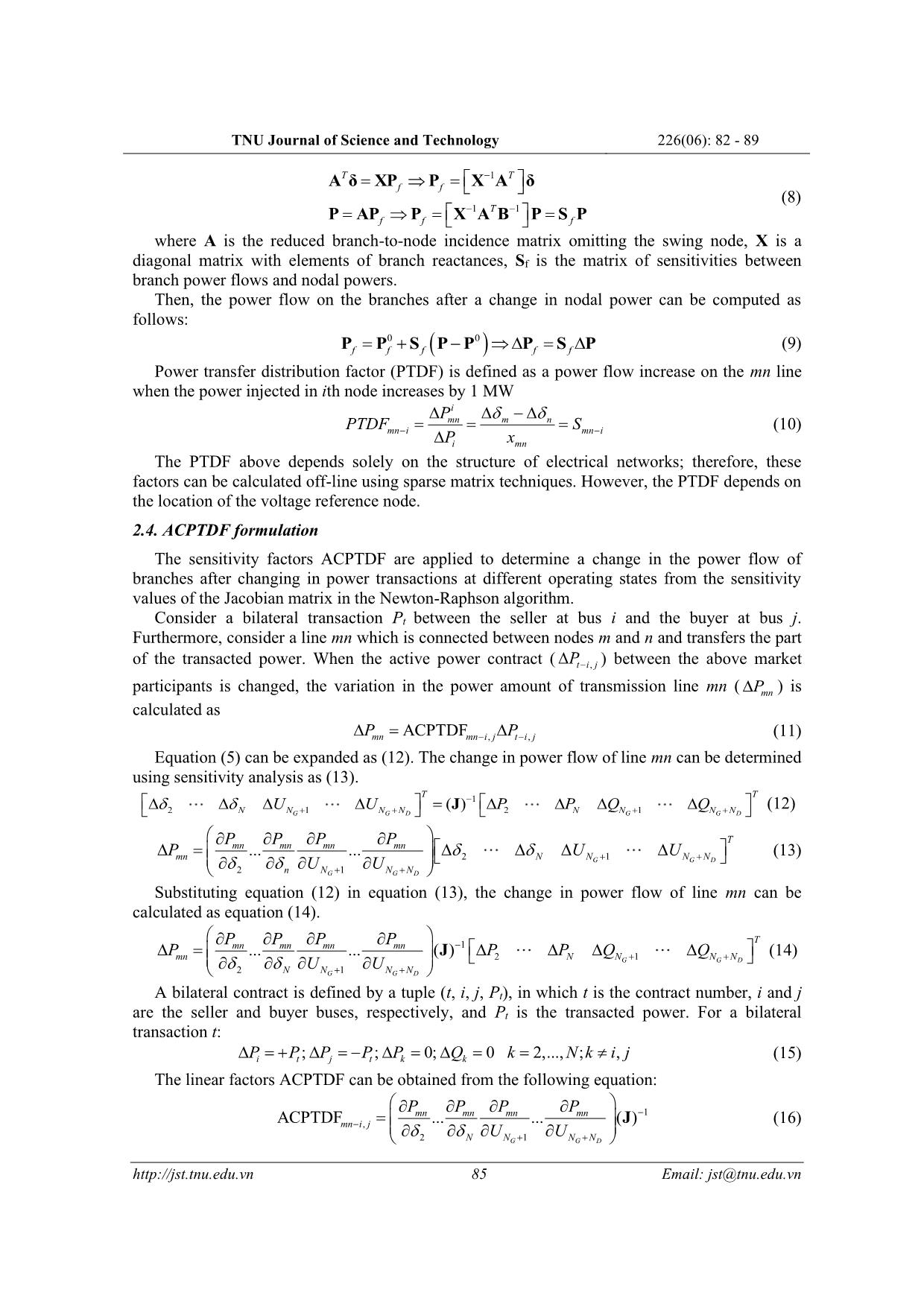
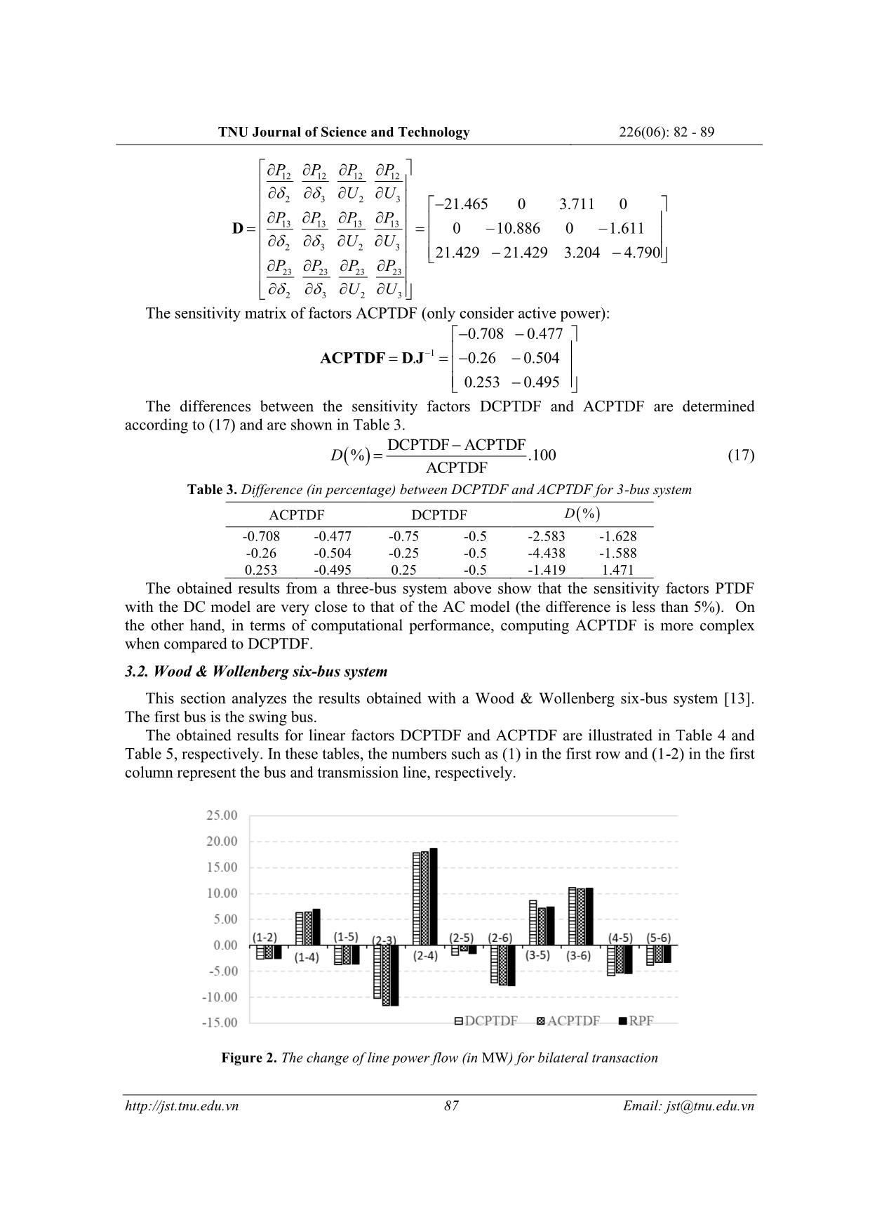
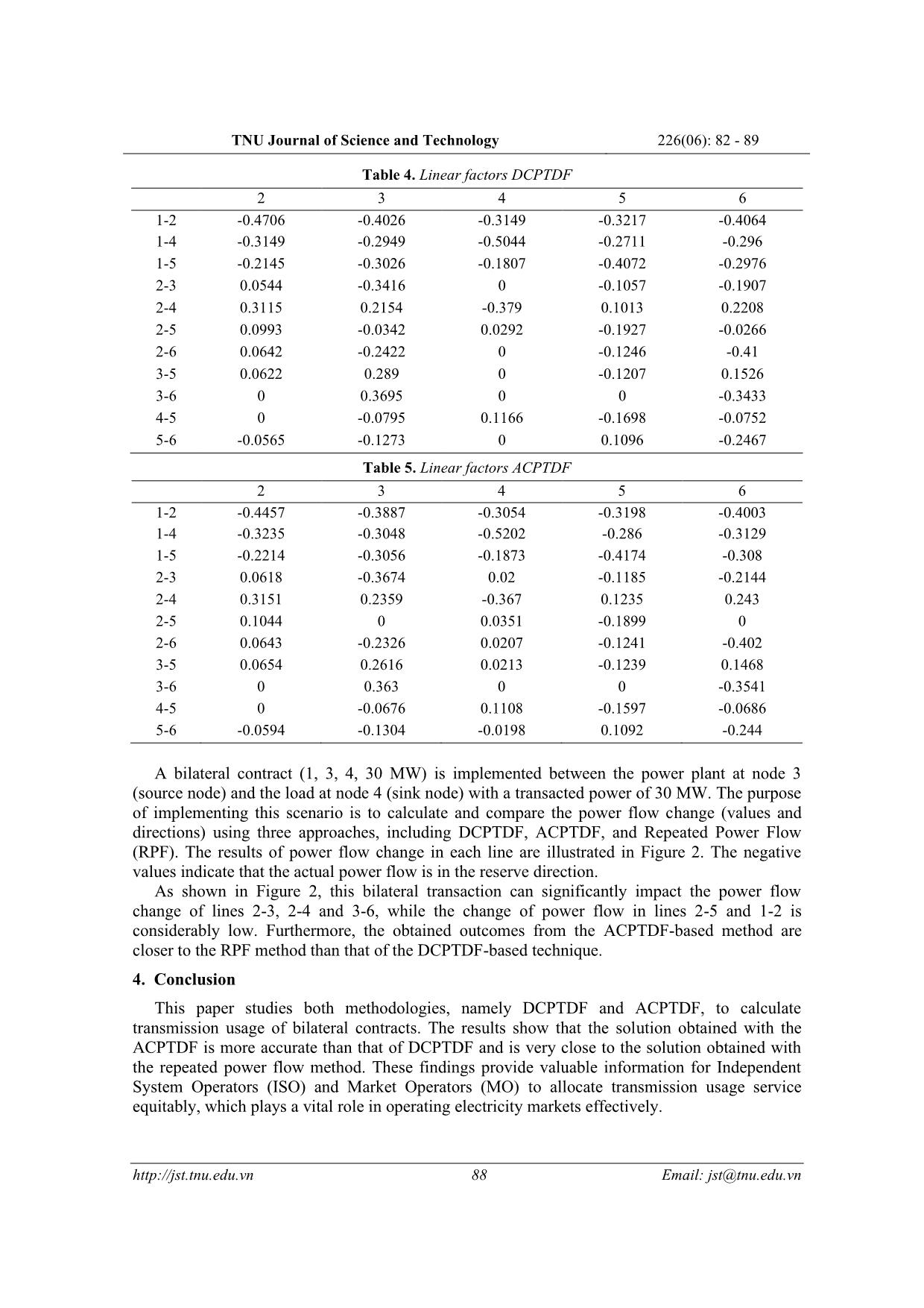
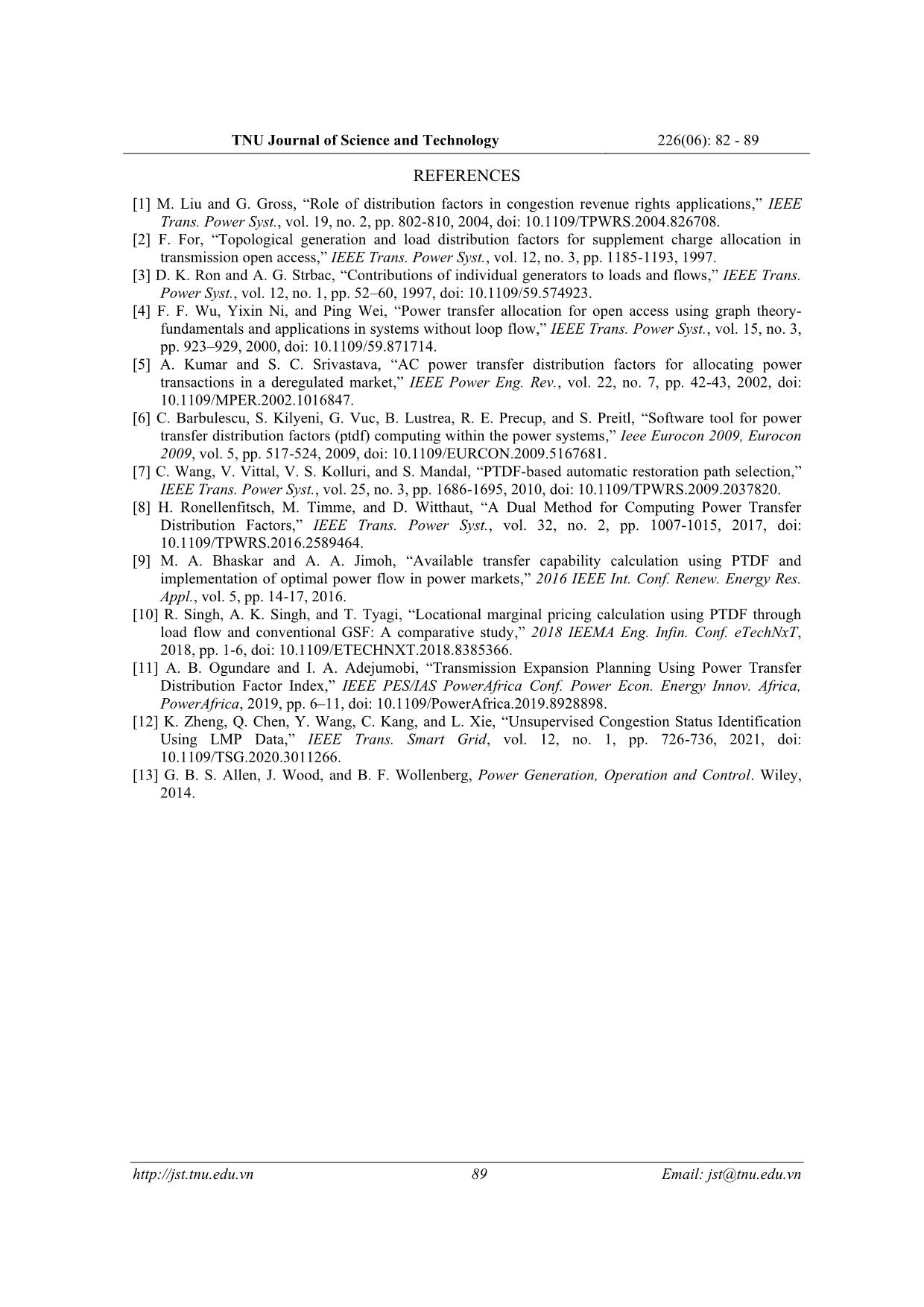
TNU Journal of Science and Technology 226(06): 82 - 89 82 Email: jst@tnu.edu.vn A COMPARATIVE STUDY OF PTDF BASED-METHODS TO DETERMINE TRANSMISSION USAGE ALLOCATION FOR BILATERAL TRANSACTIONS IN POWER MARKETS Pham Nang Van* School of Electrical Engineering - Hanoi University of Science and Technology ARTICLE INFO ABSTRACT Received: 22/02/2021 The electricity industry has been deregulated with the aim of producing competition among power market participants, which would result in considerable difficulties for power system operators. One of these challenges is that power system operators need to give participants nondiscriminatory access to transmission usage. In this study, the transacted power flow in transmission networks for bilateral transactions deploying methods based Power Transfer Distribution Factor (PTDF) was analyzed and compared. The Power Transfer Distribution Factor can be classified as DCPTDF and ACPTDF. The results from these approaches using a three bus and Wood & Wollenberg six bus systems were elaborately computed and compared. The comparison shows that leveraging factors ACPTDF to allocate transmission usage is more exact but complicated than the techniques based factors DCPTDF. The comparative study in this paper provides a comprehensive evaluation that can support power system operators to achieve nondiscrimination in power trade. Revised: 28/05/2021 Published: 31/5/2021 KEYWORDS Power markets Power transfer distribution factor (PTDF) ACPTDF Transmission usage allocation Bilateral transactions SO SÁNH CÁC PHƯƠNG PHÁP SỬ DỤNG HỆ SỐ PTDF ĐỂ PHÂN BỔ CÔNG SUẤT TRÊN LƯỚI TRUYỀN TẢI CỦA CÁC GIAO DỊCH SONG PHƯƠNG TRONG THỊ TRƯỜNG ĐIỆN Phạm Năng Văn Viện Điện - Trường Đại học Bách khoa Hà Nội THÔNG TIN BÀI BÁO TÓM TẮT Ngày nhận bài: 22/02/2021 Ngành điện đã và đang tái cấu trúc với mục đích tạo ra sự cạnh tranh giữa những người tham gia thị trường điện. Sự tái cấu trúc này dẫn đến những khó khăn đáng kể cho các đơn vị vận hành hệ thống điện. Một trong những khó khăn này là các đơn vị vận hành hệ thống điện cần cung cấp cho đơn vị tham gia thị trường quyền sử dụng lưới điện truyền tải một cách công bằng. Trong nghiên cứu này, phân bố công suất trên lưới điện truyền tải của các giao dịch song phương được phân tích và so sánh sử dụng hệ số phân bố truyền tải công suất (PTDF). Hệ số phân bố truyền tải công suất được phân loại thành DCPTDF và ACPTDF. Kết quả tính toán từ cả hai tiếp cận này sử dụng các hệ thống điện 3 nút và 6 nút Wood & Wollenberg được phân tích và so sánh. Sự so sánh cho thấy phân bổ công suất trên lưới truyền tải của các giao dịch song phương khi áp dụng hệ số ACPTDF chính xác hơn nhưng phức tạp hơn so với sử dụng hệ số DCPTDF. Kết quả nghiên cứu trong bài báo này cung cấp sự đánh giá chi tiết để hỗ trợ các đơn vị vận hành hệ thống điện đạt được sự công bằng trong hoạt động thị trường điện. Ngày hoàn thiện: 28/05/2021 Ngày đăng: 31/5/2021 TỪ KHÓA Thị trường điện Hệ số phân bố truyền tải công suất (PTDF) ACPTDF Phân bổ sử dụng truyền tải Giao dịch song phương DOI: https://doi.org/10.34238/tnu-jst.4019 Email: van.phamnang@hust.edu.vn TNU Journal of Science and Technology 226(06): 82 - 89 83 Email: jst@tnu.edu.vn 1. Introduction Power deregulation aims at creating competitive electricity markets. In these markets, consumers have options to purchase electricity from various producers. Therefore, efficient transmission usage allocation needs to be studied to implement power transfer between diverse consumers and producers. Determining the extent of transmission service use aims to (1) equitably allocate transmission costs to those participating in the power grids and (2) calculate loss indicators to operate transmission grids more reliably and efficiently. Furthermore, fair transmission service is also essential in giving signals to the marketplace for long-term investment. Applying power flow methods such as Newton-Raphson, Fast Decoupled Power Flow (FDPF) to accurately compute the transmission usage level of market participants is complicated and time-consuming [1]. There are some effective approaches developed to deal with the problem of transmission usage allocation. In [2], the author proposed a topology-based approach to determine the share of a particular generator or demand in the power flow of each line branch. The paper [3] developed another technique based on concepts such as the domain of a generator, commons, links and state graph. The procedure using graph theory was put forward in [4] to determine injection factors of individual generators to line branch flows and withdrawal factors of individual demands from line flows. Authors in [5] introduced an AC power transfer distribution factor (PTDF)-based method to allocate the real power flow on transmission lines. PTDFs are coefficients of the linea ... rch has made major contributions as follow: • Rigorously present a step-by-step procedure to calculate ACPTDF using a three-bus system; • Compare the findings of transmission usage allocation from both kinds of sensitivity factors PTDF. The paper is structured into four sections. Section 2 presents the Newton-Raphson method, formulations of DCPTDF and ACPTDF. Numerical results and discussions using three-bus and Wood & Wollenberg six-bus systems are given in Section 3, and the conclusions are inferred in Section 4. 2. Methodology 2.1. Newton-Raphson method This section addresses the formulation and Newton-Raphson solution to the power flow problem. The complex current injected to the bus i is expressed as follow: 1 1,2,..., n i ik k k I Y U i N = = = (1) TNU Journal of Science and Technology 226(06): 82 - 89 84 Email: jst@tnu.edu.vn where kU is the complex voltage at node k; ik ik ikY G jB= + is the ikth element of the admittance matrix, and N is the total nodes of the power system with GN generator buses and DN load nodes. Bus 1 is chosen as the voltage reference bus. The complex power at ith bus: * * * 1 1 n n i i ik k i ik k k k S U Y U U Y U i = = = = (2) Using rectangular coordinates for elements of the admittance matrix and polar form for voltages leads to: ( )ik 1 ( ) cos sin n i i k ik ik ik k S U U G jB j i = = − + (3) where ik is the difference between the phase angles of nodes i and k; ,i kU U is the voltage magnitude at bus i and k, respectively. Split (3) into 2n real equations: 1 1 ( cos sin ) ( sin cos ) n i i k ik ik ik ik k n i i k ik ik ik ik k P U U G B Q U U G B = = = + = − (4) The Newton-Raphson (NR) successively improves unknown values through the first-order approximation of the involved non-linear equations. According to NR method, with initial values, corrections are obtained by solving the linear equation system: ( ) ( ) ( )r r r = P δ J Q U (5) where J is the Jacobian matrix; ΔP and ΔQ are the difference between the specified power and the power computed with the most recent values. The iteration continues until all the mismatch vector of power in absolute value lower than the pre-specified tolerance. 2.2. DC Power Flow This DC power flow (DCPF) method is developed with assumptions as follows: • the voltage magnitude at all buses is equal to 1; • the phase angle difference corresponding to adjacent buses are small; • series resistance is ignored. With these hypotheses, the real power flow is simplified to ( ) 1 ik i k ik P x = − (6) where ikx is the reactance of ikth branch. The linear relationship between nodal power injection and voltage angle, according to the DCPF method, is written as follows: ( ) 1 i ik i k k k ik P P x = = − (7) 2.3. DCPTDF formulation Equation (7) can be rewritten in matrix form as P = Bδ . The relationship between branch power flow fP and nodal injected power P can be obtained by eliminating phase angles: TNU Journal of Science and Technology 226(06): 82 - 89 85 Email: jst@tnu.edu.vn 1 1 1 T T f f T f f f − − − = = = = = A δ XP P X A δ P AP P X A B P S P (8) where A is the reduced branch-to-node incidence matrix omitting the swing node, X is a diagonal matrix with elements of branch reactances, Sf is the matrix of sensitivities between branch power flows and nodal powers. Then, the power flow on the branches after a change in nodal power can be computed as follows: ( )0 0f f f f f= + − = P P S P P P S P (9) Power transfer distribution factor (PTDF) is defined as a power flow increase on the mn line when the power injected in ith node increases by 1 MW i mn m n mn i mn i i mn P PTDF S P x − − − = = = (10) The PTDF above depends solely on the structure of electrical networks; therefore, these factors can be calculated off-line using sparse matrix techniques. However, the PTDF depends on the location of the voltage reference node. 2.4. ACPTDF formulation The sensitivity factors ACPTDF are applied to determine a change in the power flow of branches after changing in power transactions at different operating states from the sensitivity values of the Jacobian matrix in the Newton-Raphson algorithm. Consider a bilateral transaction Pt between the seller at bus i and the buyer at bus j. Furthermore, consider a line mn which is connected between nodes m and n and transfers the part of the transacted power. When the active power contract ( ,t i jP− ) between the above market participants is changed, the variation in the power amount of transmission line mn ( mnP ) is calculated as , ,ACPTDFmn mn i j t i jP P− − = (11) Equation (5) can be expanded as (12). The change in power flow of line mn can be determined using sensitivity analysis as (13). 1 2 1 2 1( )G G D G G D T T N N N N N N N NU U P P Q Q − + + + + = J (12) 2 1 2 1 ... ... G G D G G D T mn mn mn mn mn N N N N n N N N P P P P P U U U U + + + + = (13) Substituting equation (12) in equation (13), the change in power flow of line mn can be calculated as equation (14). 1 2 1 2 1 ... ... ( ) G G D G G D T mn mn mn mn mn N N N N N N N N P P P P P P P Q Q U U − + + + + = J (14) A bilateral contract is defined by a tuple (t, i, j, Pt), in which t is the contract number, i and j are the seller and buyer buses, respectively, and Pt is the transacted power. For a bilateral transaction t: ; ; 0; 0 2,..., ; ,i t j t k kP P P P P Q k N k i j = + = − = = = (15) The linear factors ACPTDF can be obtained from the following equation: 1 , 2 1 ACPTDF ... ... ( ) G G D mn mn mn mn mn i j N N N N P P P P U U − − + + = J (16) TNU Journal of Science and Technology 226(06): 82 - 89 86 Email: jst@tnu.edu.vn Incorporating (15) into (14), the change in branch power flow due to bilateral transactions can be determined. The ACPTDF are determined at a base power flow condition and are deployed to compute the change in power flow of transmission lines at other operational conditions. 3. Results and discussion In this section, the transmission usage allocation using ACPTDF and ACPTDF methods is calculated on three-bus and Wood & Wollenberg six bus systems. 3.1. Three-bus system The diagram of a three-bus system is depicted in Figure 1. The first bus is considered the slack bus. The bus data and line data are shown in Table 1 and Table 2, respectively. Table 1. Bus data for three-bus system Bus U PD QD PG QG 1 1.05 0 0 - - 2 1.05 6 3 3.8 - 3 1.07 2 1.2 1.7 - Table 2. Line data for three-bus system Line r x b/2 1-2 0.02 0.1 0.01 1-3 0.02 0.1 0.01 2-3 0.01 0.05 0.005 2 1 3 G1G2 G3 Figure 1. Three-bus system 3.1.1 Sensitivity factors DCPTDF Matrices A, X and B are as follows 0.05 0 0 0 0.1 0 0 0 0.05 = X 1 0 1 0 1 1 − = − − A 40 20 20 30 − = − B 1 1 0.75 0.5 [ ] [ ] 0.25 0.5 0.25 0.5 T f − − − − = = = − − − DCPTDF S X A B 3.1.2 Sensitivity factors ACPTDF The final results of bus voltages are 1 2 31,05; 1,05 0,0771; 1,07 0,0399U U U= = − = − Jacobian matrix: 2 2 2 2 2 3 2 3 3 3 3 3 2 3 2 3 2 2 2 2 2 3 2 3 3 3 3 3 2 3 2 3 10.99 5.13 40.49 20.03 3.52 6 . .11 20.71 42.24 21.43 5 7 4.79 21.75 32.46 3.35 6.64 P P P P U U P P P P U U Q Q Q Q U U Q Q Q Q U U − = = − − − − − − − J 31.36 The sensitivity matrix of line power flow with respect to state variables can be expressed as follows: TNU Journal of Science and Technology 226(06): 82 - 89 87 Email: jst@tnu.edu.vn 12 12 12 12 2 3 2 3 13 13 13 13 2 3 2 3 23 23 23 23 2 3 2 3 21.465 0 3.711 0 10.886 0 1.611 21.429 21. 0 0 429 3.2 4 4.790 P P P P U U P P P P U U P P P P U U = = − − − − − D The sensitivity matrix of factors ACPTDF (only consider active power): 1 0.708 0.477 0.26 0.504 0.253 0.495 . − = = − − − − − ACPTDF D J The differences between the sensitivity factors DCPTDF and ACPTDF are determined according to (17) and are shown in Table 3. ( ) DCPTDF ACPTDF % .100 ACPTDF D − = (17) Table 3. Difference (in percentage) between DCPTDF and ACPTDF for 3-bus system ACPTDF DCPTDF ( )%D -0.708 -0.477 -0.75 -0.5 -2.583 -1.628 -0.26 -0.504 -0.25 -0.5 -4.438 -1.588 0.253 -0.495 0.25 -0.5 -1.419 1.471 The obtained results from a three-bus system above show that the sensitivity factors PTDF with the DC model are very close to that of the AC model (the difference is less than 5%). On the other hand, in terms of computational performance, computing ACPTDF is more complex when compared to DCPTDF. 3.2. Wood & Wollenberg six-bus system This section analyzes the results obtained with a Wood & Wollenberg six-bus system [13]. The first bus is the swing bus. The obtained results for linear factors DCPTDF and ACPTDF are illustrated in Table 4 and Table 5, respectively. In these tables, the numbers such as (1) in the first row and (1-2) in the first column represent the bus and transmission line, respectively. Figure 2. The change of line power flow (in MW) for bilateral transaction TNU Journal of Science and Technology 226(06): 82 - 89 88 Email: jst@tnu.edu.vn Table 4. Linear factors DCPTDF 2 3 4 5 6 1-2 -0.4706 -0.4026 -0.3149 -0.3217 -0.4064 1-4 -0.3149 -0.2949 -0.5044 -0.2711 -0.296 1-5 -0.2145 -0.3026 -0.1807 -0.4072 -0.2976 2-3 0.0544 -0.3416 0 -0.1057 -0.1907 2-4 0.3115 0.2154 -0.379 0.1013 0.2208 2-5 0.0993 -0.0342 0.0292 -0.1927 -0.0266 2-6 0.0642 -0.2422 0 -0.1246 -0.41 3-5 0.0622 0.289 0 -0.1207 0.1526 3-6 0 0.3695 0 0 -0.3433 4-5 0 -0.0795 0.1166 -0.1698 -0.0752 5-6 -0.0565 -0.1273 0 0.1096 -0.2467 Table 5. Linear factors ACPTDF 2 3 4 5 6 1-2 -0.4457 -0.3887 -0.3054 -0.3198 -0.4003 1-4 -0.3235 -0.3048 -0.5202 -0.286 -0.3129 1-5 -0.2214 -0.3056 -0.1873 -0.4174 -0.308 2-3 0.0618 -0.3674 0.02 -0.1185 -0.2144 2-4 0.3151 0.2359 -0.367 0.1235 0.243 2-5 0.1044 0 0.0351 -0.1899 0 2-6 0.0643 -0.2326 0.0207 -0.1241 -0.402 3-5 0.0654 0.2616 0.0213 -0.1239 0.1468 3-6 0 0.363 0 0 -0.3541 4-5 0 -0.0676 0.1108 -0.1597 -0.0686 5-6 -0.0594 -0.1304 -0.0198 0.1092 -0.244 A bilateral contract (1, 3, 4, 30 MW) is implemented between the power plant at node 3 (source node) and the load at node 4 (sink node) with a transacted power of 30 MW. The purpose of implementing this scenario is to calculate and compare the power flow change (values and directions) using three approaches, including DCPTDF, ACPTDF, and Repeated Power Flow (RPF). The results of power flow change in each line are illustrated in Figure 2. The negative values indicate that the actual power flow is in the reserve direction. As shown in Figure 2, this bilateral transaction can significantly impact the power flow change of lines 2-3, 2-4 and 3-6, while the change of power flow in lines 2-5 and 1-2 is considerably low. Furthermore, the obtained outcomes from the ACPTDF-based method are closer to the RPF method than that of the DCPTDF-based technique. 4. Conclusion This paper studies both methodologies, namely DCPTDF and ACPTDF, to calculate transmission usage of bilateral contracts. The results show that the solution obtained with the ACPTDF is more accurate than that of DCPTDF and is very close to the solution obtained with the repeated power flow method. These findings provide valuable information for Independent System Operators (ISO) and Market Operators (MO) to allocate transmission usage service equitably, which plays a vital role in operating electricity markets effectively. TNU Journal of Science and Technology 226(06): 82 - 89 89 Email: jst@tnu.edu.vn REFERENCES [1] M. Liu and G. Gross, “Role of distribution factors in congestion revenue rights applications,” IEEE Trans. Power Syst., vol. 19, no. 2, pp. 802-810, 2004, doi: 10.1109/TPWRS.2004.826708. [2] F. For, “Topological generation and load distribution factors for supplement charge allocation in transmission open access,” IEEE Trans. Power Syst., vol. 12, no. 3, pp. 1185-1193, 1997. [3] D. K. Ron and A. G. Strbac, “Contributions of individual generators to loads and flows,” IEEE Trans. Power Syst., vol. 12, no. 1, pp. 52–60, 1997, doi: 10.1109/59.574923. [4] F. F. Wu, Yixin Ni, and Ping Wei, “Power transfer allocation for open access using graph theory- fundamentals and applications in systems without loop flow,” IEEE Trans. Power Syst., vol. 15, no. 3, pp. 923–929, 2000, doi: 10.1109/59.871714. [5] A. Kumar and S. C. Srivastava, “AC power transfer distribution factors for allocating power transactions in a deregulated market,” IEEE Power Eng. Rev., vol. 22, no. 7, pp. 42-43, 2002, doi: 10.1109/MPER.2002.1016847. [6] C. Barbulescu, S. Kilyeni, G. Vuc, B. Lustrea, R. E. Precup, and S. Preitl, “Software tool for power transfer distribution factors (ptdf) computing within the power systems,” Ieee Eurocon 2009, Eurocon 2009, vol. 5, pp. 517-524, 2009, doi: 10.1109/EURCON.2009.5167681. [7] C. Wang, V. Vittal, V. S. Kolluri, and S. Mandal, “PTDF-based automatic restoration path selection,” IEEE Trans. Power Syst., vol. 25, no. 3, pp. 1686-1695, 2010, doi: 10.1109/TPWRS.2009.2037820. [8] H. Ronellenfitsch, M. Timme, and D. Witthaut, “A Dual Method for Computing Power Transfer Distribution Factors,” IEEE Trans. Power Syst., vol. 32, no. 2, pp. 1007-1015, 2017, doi: 10.1109/TPWRS.2016.2589464. [9] M. A. Bhaskar and A. A. Jimoh, “Available transfer capability calculation using PTDF and implementation of optimal power flow in power markets,” 2016 IEEE Int. Conf. Renew. Energy Res. Appl., vol. 5, pp. 14-17, 2016. [10] R. Singh, A. K. Singh, and T. Tyagi, “Locational marginal pricing calculation using PTDF through load flow and conventional GSF: A comparative study,” 2018 IEEMA Eng. Infin. Conf. eTechNxT, 2018, pp. 1-6, doi: 10.1109/ETECHNXT.2018.8385366. [11] A. B. Ogundare and I. A. Adejumobi, “Transmission Expansion Planning Using Power Transfer Distribution Factor Index,” IEEE PES/IAS PowerAfrica Conf. Power Econ. Energy Innov. Africa, PowerAfrica, 2019, pp. 6–11, doi: 10.1109/PowerAfrica.2019.8928898. [12] K. Zheng, Q. Chen, Y. Wang, C. Kang, and L. Xie, “Unsupervised Congestion Status Identification Using LMP Data,” IEEE Trans. Smart Grid, vol. 12, no. 1, pp. 726-736, 2021, doi: 10.1109/TSG.2020.3011266. [13] G. B. S. Allen, J. Wood, and B. F. Wollenberg, Power Generation, Operation and Control. Wiley, 2014.
File đính kèm:
 a_comparative_study_of_ptdf_based_methods_to_determine_trans.pdf

