A simple power – based direction of arrival sensor
As can be seen, the world is at an explosive increasing rate with mobile communication.
Array antennas and base - stations are playing an important role to meet the demands of global
user equipments. With a large number of the user nowadays, adaptive signal processing array
known as the smart antenna, which commonly used in new generations mobile systems, can
locate mobile users by using DoA estimation techniques. The goal of direction of arrival (DoA)
estimation is to use the data received on the downlink at the base-station to estimate the
directions of the signals from the desired mobile users as well as the directions of interference
signals. The result of DoA estimation is used to determine the location of users so that the
maximum power towards the desired users while radiation nulls in the direction of interference
signals. Therefore, direction finding (DF) for multiple wireless devices is paid more attention in
communication applications. For examples, in the military, it is required to determine accurately
the position of a potential enemy. It can be accomplished by finding the direction of the coming
wave. Another application, in robotic technology, DF helps robots be aware of the around
obstructions without the external remote control. Direction of arrival (DoA) estimation was
found out and developed since the years of the last century. Watson Watt principle is a power –
based method in which the DoA is obtained from the ratio of the amplitude of received signals
applied on the x and y plane. The other method, which is phase – based, is accomplished by the
output signals from interferometer that helps to know the phase – difference of input signals [1].
The DoA estimation algorithm – based then is applied to determine the direction of the incident
wave. In [3], a low – complexity DoA estimation based on compressed MUSIC is investigated
with its performance analysis.
Trang 1
Trang 2
Trang 3
Trang 4
Trang 5
Trang 6
Trang 7
Tóm tắt nội dung tài liệu: A simple power – based direction of arrival sensor
Kỹ thuật điều khiển & Điện tử
 48 V. T. Nga, L. M. Thuy, “A simple power - based Direction of Arrival sensor.”
A SIMPLE POWER – BASED DIRECTION OF ARRIVAL SENSOR
Vu Thi Nga, Le Minh Thuy
*
Abstract: In this paper, a simple power - based Direction of Arrival (DoA) sensor is
investigated. This sensor is applied in direction finding systems working at 2.6 GHz. The
proposed sensor can determine the DoA via a simple formula compared to the algorithms
– based methods. The sensor structure consists of simple components: two receiving
antennas and a power dividers which have a good isolation between output ports based on
hybrid couplers (HCs). With the range of simulation DoA from 0
o
 to 35
o
, the proposed
sensor yields the error of less than 5
o
.
Keywords: Direction finding (DF); Direction of Arrival (DoA); Power – based; Hybrid coupler (HC).
1. INTRODUCTION
As can be seen, the world is at an explosive increasing rate with mobile communication.
Array antennas and base - stations are playing an important role to meet the demands of global
user equipments. With a large number of the user nowadays, adaptive signal processing array
known as the smart antenna, which commonly used in new generations mobile systems, can
locate mobile users by using DoA estimation techniques. The goal of direction of arrival (DoA)
estimation is to use the data received on the downlink at the base-station to estimate the
directions of the signals from the desired mobile users as well as the directions of interference
signals. The result of DoA estimation is used to determine the location of users so that the
maximum power towards the desired users while radiation nulls in the direction of interference
signals. Therefore, direction finding (DF) for multiple wireless devices is paid more attention in
communication applications. For examples, in the military, it is required to determine accurately
the position of a potential enemy. It can be accomplished by finding the direction of the coming
wave. Another application, in robotic technology, DF helps robots be aware of the around
obstructions without the external remote control. Direction of arrival (DoA) estimation was
found out and developed since the years of the last century. Watson Watt principle is a power –
based method in which the DoA is obtained from the ratio of the amplitude of received signals
applied on the x and y plane. The other method, which is phase – based, is accomplished by the
output signals from interferometer that helps to know the phase – difference of input signals [1].
The DoA estimation algorithm – based then is applied to determine the direction of the incident
wave. In [3], a low – complexity DoA estimation based on compressed MUSIC is investigated
with its performance analysis. Performances of other algorithms which are commonly used
currently such as MVDR, ESPRIT,... are known in [4], [5]. These methods are fully digital and
complicated to find out the relationship between the direction of the incident wave and received
signals. To deal with this problem, some recent publications proposed simpler approaches to
obtain the direction of arrival. One of those, the interferometry – based DoA detection system in
[2] whose structure composes of three receiving antennas, one hybrid coupler, two rat – race
couplers. The estimation of the angle of arrival is deduced from the output DC voltages that are
proportional to the magnitude of RF signals at their inputs. With the distance between the two
consecutive antennas is half of the wavelength in free space, the unambiguity range of angle of
arrival in the interval [-30
o
; 30
o
] and the range is [-14.4
o
; 14.4
o
] if decrease to a quater of
wavelength in free space.
In this work, we present a simple power – based sensor to obtain the DoA of any incident wave.
Compared to the traditional methods which is used in most applications currently, this sensor has
simple structure, low – cost, and good accuracy. The DoA of an incident wave is determined via a
proposed simple equation of the powers at output ports of hybrid couplers (HCs) that are received
Nghiên cứu khoa học công nghệ
 Tạp chí Nghiên cứu KH&CN quân sự, Số 73, 06 - 2021 49
from two receiving antennas. To the best of our knowledge, the simple, low cost and fully analog
DOA sensor with the error of less than 5
o
 has not been published before.
2. PROPOSED DOA SENSOR
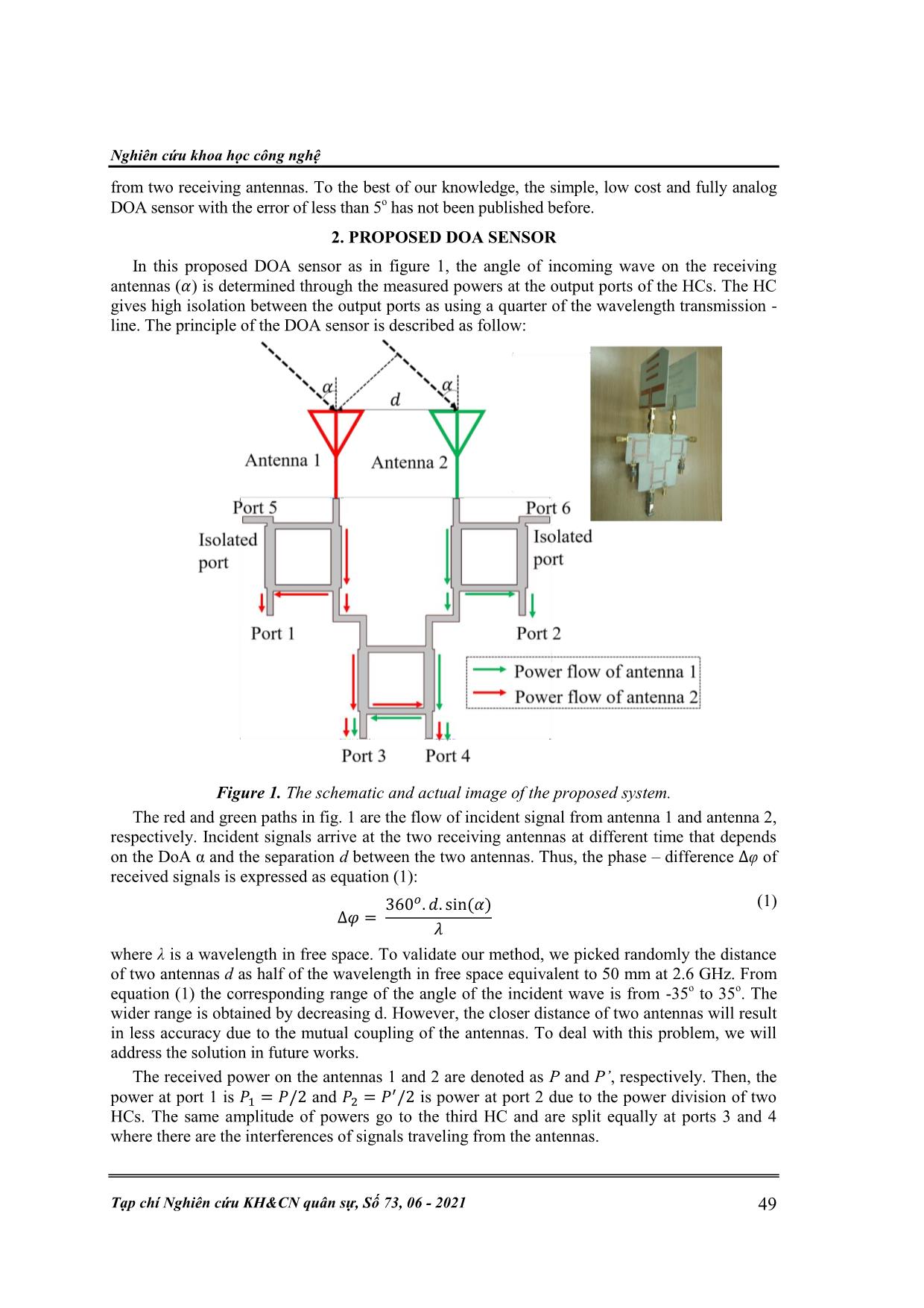
In this proposed DOA sensor as in figure 1, the angle of incoming wave on the receiving
antennas ( ) is determined through the measured powers at the output ports of the HCs. The HC
gives high isolation between the output ports as using a quarter of the wavelength transmission -
line. The principle of the DOA sensor is described as follow:
Figure 1. The schematic and actual image of the proposed system.
The red and green paths in fig. 1 are the flow of incident signal from antenna 1 and antenna 2,
respectively. Incident signals arrive at the two receiving antennas at different time that depends
on the DoA α and the separation d between the two antennas. Thus, the phase – difference φ of
received signals is expressed as equation (1):
(1)
where λ is a wavelength in free space. To validate our method, we picked randomly the distance
of two antennas d as half of the wavelength in free space equivalent to 50 mm at 2.6 GHz. From
equation (1) the corresponding range of the angle of the incident wave is from -35
o
 to 35
o
. The
wider range is obtained by decreasing d. However, the closer distance of two antennas will result
in less accuracy due to the mutual coupling of the antennas. To deal with this problem, we will
address the solution in future works.
The received power on the antennas 1 and 2 are denoted as P and P’, respectively. Then, the
power at port 1 is and
 is power at port 2 due to the power division of two
HCs. The same amplitude of powers go to the third HC and are split equally at ports 3 and 4
where there are the interferences of signals traveling from the antennas.
Kỹ thuật điều khiển & Điện tử
 50 V. T. Nga, L. M. Thuy, “A simple power - based Direction of Arrival sensor.”
We then examined the interference at port 3. Similarity for port 4. Denote I and I’ are the
amplitude of the currents signal interfering at port 3. In HC, the input- impedance seen from each
port is 50 Ω. Then, the input power at the port is the equation of square of signal current
amplitude multiplied by the real part of load impedance at the port. Thus, I and I’ are expressed
by the following equations:
(2)
 (3)
The current I3
at port 3 is the addition vector of I and I’ as in fig. 2. The phase – difference of
the two currents is ( due to the property of the HC. Therefore, the amplitude of I3 is
calculated using the Law of Cosine:
 (4)
Figure 2. The formula of current at port 3.
Similarly, the output power at port 3 is expressed as:
 (5)
Thus, the phase – difference is deduced as:
√
(6)
Then, by using equations (1) and (6) DoA α is determined from the measured output powers
at port 1, port 2, and port 3 or port 4.
The power ratio at two output ports of the first two HCs must be designed 1:1 with all DoA
sensor. The reason why HC is chosen instead of the T – junction is its good isolation. To design
the DOA sensor, the HCs must be designed.
In the next section, we will present the design of the proposed sensor.
3. SIMULATION RESULTS
Firstly, the HCs operating at the frequency of 2.6 GHz are designed using Advanced Design
Simulation (ADS) software. As mentioned before, the HCs has four – ports: one input port, two
output ports and two isolated ports that are terminated with a matched load of 50 Ω, it helps to
split the input power into equal part and 90
o
 phase - difference at output ports. Here, we choose
the hybrid branch – line coupler which consists of two main transmission – lines physically
coupled together with two branches between them. The separation of lines is theoretically .
The characteristic impedance of the main lines and branch lines are respectively 35 Ω and 50 Ω
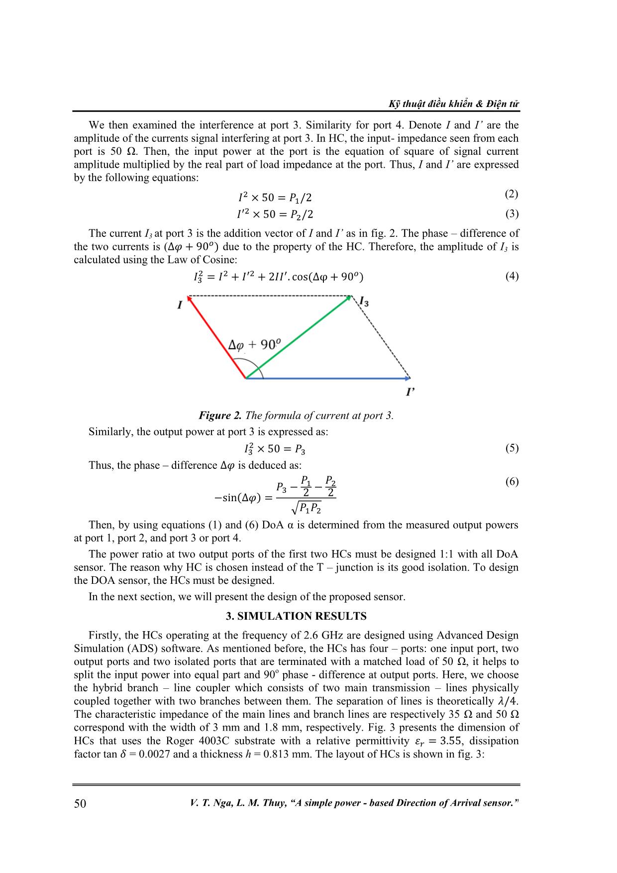
correspond with the width of 3 mm and 1.8 mm, respectively. Fig. 3 presents the dimension of
HCs that uses the Roger 4003C substrate with a relative permittivity , dissipation
factor tan = 0.0027 and a thickness h = 0.813 mm. The layout of HCs is shown in fig. 3:
Nghiên cứu khoa học công nghệ
 Tạp chí Nghiên cứu KH&CN quân sự, Số 73, 06 - 2021 51
Substrate :
h = 0.813 mm
Dimension
parameters of
HCs:
d = 50 mm
l = 17 mm
w1 = 3 mm
w2 = 1.8 mm
Figure 3. The layout of the proposed HCs.
According to the principle of the proposed sensor in section 2, the received power of antenna
1 and antenna 2 are respectively modeled as port 7 and port 8 as in fig. 3. The S – parameters
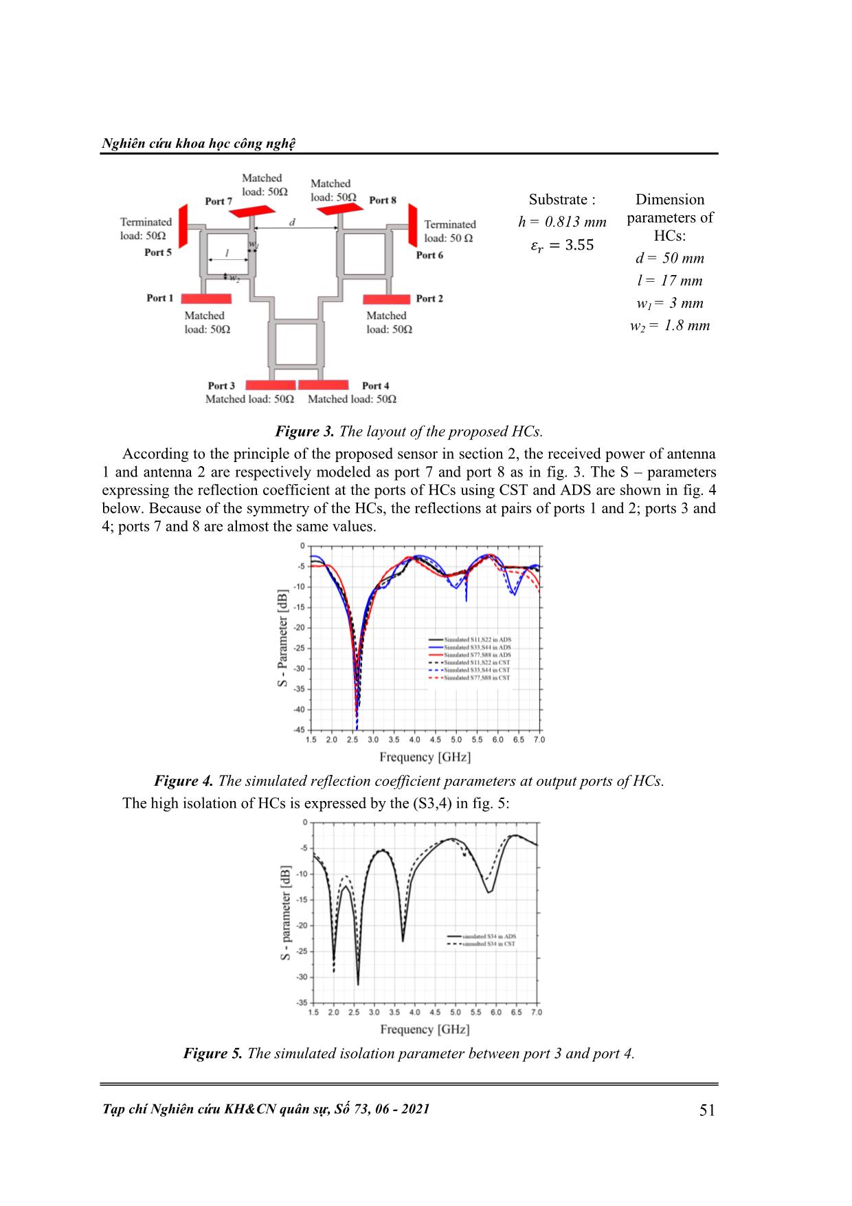
expressing the reflection coefficient at the ports of HCs using CST and ADS are shown in fig. 4
below. Because of the symmetry of the HCs, the reflections at pairs of ports 1 and 2; ports 3 and
4; ports 7 and 8 are almost the same values.
Figure 4. The simulated reflection coefficient parameters at output ports of HCs.
The high isolation of HCs is expressed by the (S3,4) in fig. 5:
Figure 5. The simulated isolation parameter between port 3 and port 4.
Kỹ thuật điều khiển & Điện tử
 52 V. T. Nga, L. M. Thuy, “A simple power - based Direction of Arrival sensor.”
From fig. 4 and fig. 5, the reflection coefficient parameters in both softwares (ADS and CST)
are Sii < -30 dB (i=1, 2, 3, 4, 7, 8) and the isolation parameter S34 is also approximately -30 dB at
2.6 GHz. These S - parameters show that the HCs is well-matched impedance and have good
isolation which is one of the most features we need about the power divisions for this sensor.
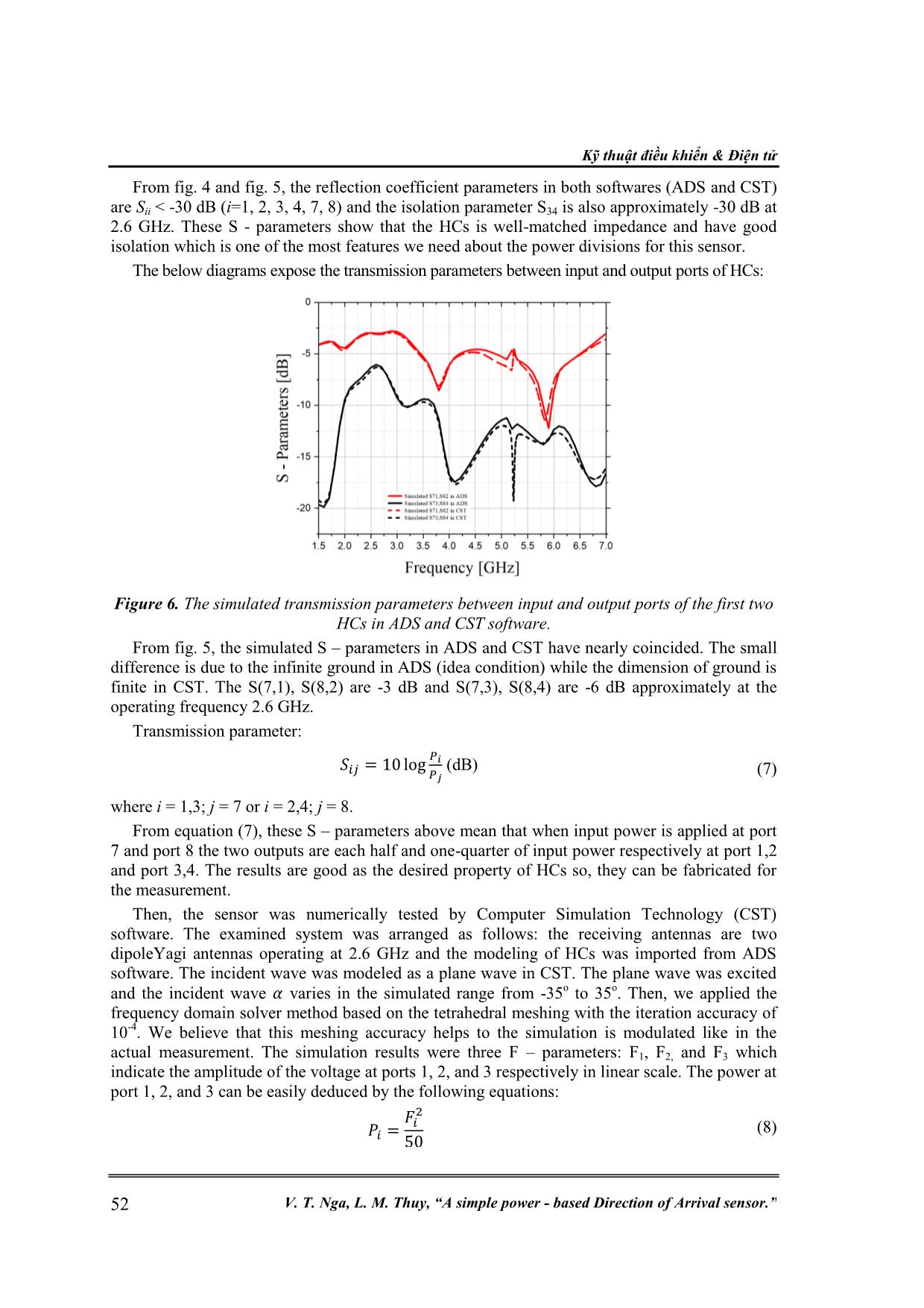
The below diagrams expose the transmission parameters between input and output ports of HCs:
Figure 6. The simulated transmission parameters between input and output ports of the first two
HCs in ADS and CST software.
From fig. 5, the simulated S – parameters in ADS and CST have nearly coincided. The small
difference is due to the infinite ground in ADS (idea condition) while the dimension of ground is
finite in CST. The S(7,1), S(8,2) are -3 dB and S(7,3), S(8,4) are -6 dB approximately at the
operating frequency 2.6 GHz.
Transmission parameter:
 (dB) (7)
where i = 1,3; j = 7 or i = 2,4; j = 8.
From equation (7), these S – parameters above mean that when input power is applied at port
7 and port 8 the two outputs are each half and one-quarter of input power respectively at port 1,2
and port 3,4. The results are good as the desired property of HCs so, they can be fabricated for
the measurement.
Then, the sensor was numerically tested by Computer Simulation Technology (CST)
software. The examined system was arranged as follows: the receiving antennas are two
dipoleYagi antennas operating at 2.6 GHz and the modeling of HCs was imported from ADS
software. The incident wave was modeled as a plane wave in CST. The plane wave was excited
and the incident wave varies in the simulated range from -35o to 35o. Then, we applied the
frequency domain solver method based on the tetrahedral meshing with the iteration accuracy of
10
-4
. We believe that this meshing accuracy helps to the simulation is modulated like in the
actual measurement. The simulation results were three F – parameters: F1, F2, and F3 which
indicate the amplitude of the voltage at ports 1, 2, and 3 respectively in linear scale. The power at
port 1, 2, and 3 can be easily deduced by the following equations:
 (8)
Nghiên cứu khoa học công nghệ
 Tạp chí Nghiên cứu KH&CN quân sự, Số 73, 06 - 2021 53
where i = 1,2,3.
Thus, the phase – difference is expressed as (8) by the F – parameters:
 (9)
Where F1, F2, and F3 are the F – parameter at port 1, port 2, and port 3 respectively.
By applying the simulated values of F1, F2, and F3 into equation (8), the phase - difference is
calculated. Thus, the DoA α is easily estimated from equation (1). It is mentioned that because of
the nature of the sine function of (8), the sine values strictly increase in range of -90
o
 to 90
o
, the
 φ in our simulation is in this range. Due to the distance of antennas is chosen as 50mm,
according to (1) it is deduced that the range of confidence interval examination DoA is from -35
o
to 35
o
. The estimated angle is compared to the incident wave angle by the error.
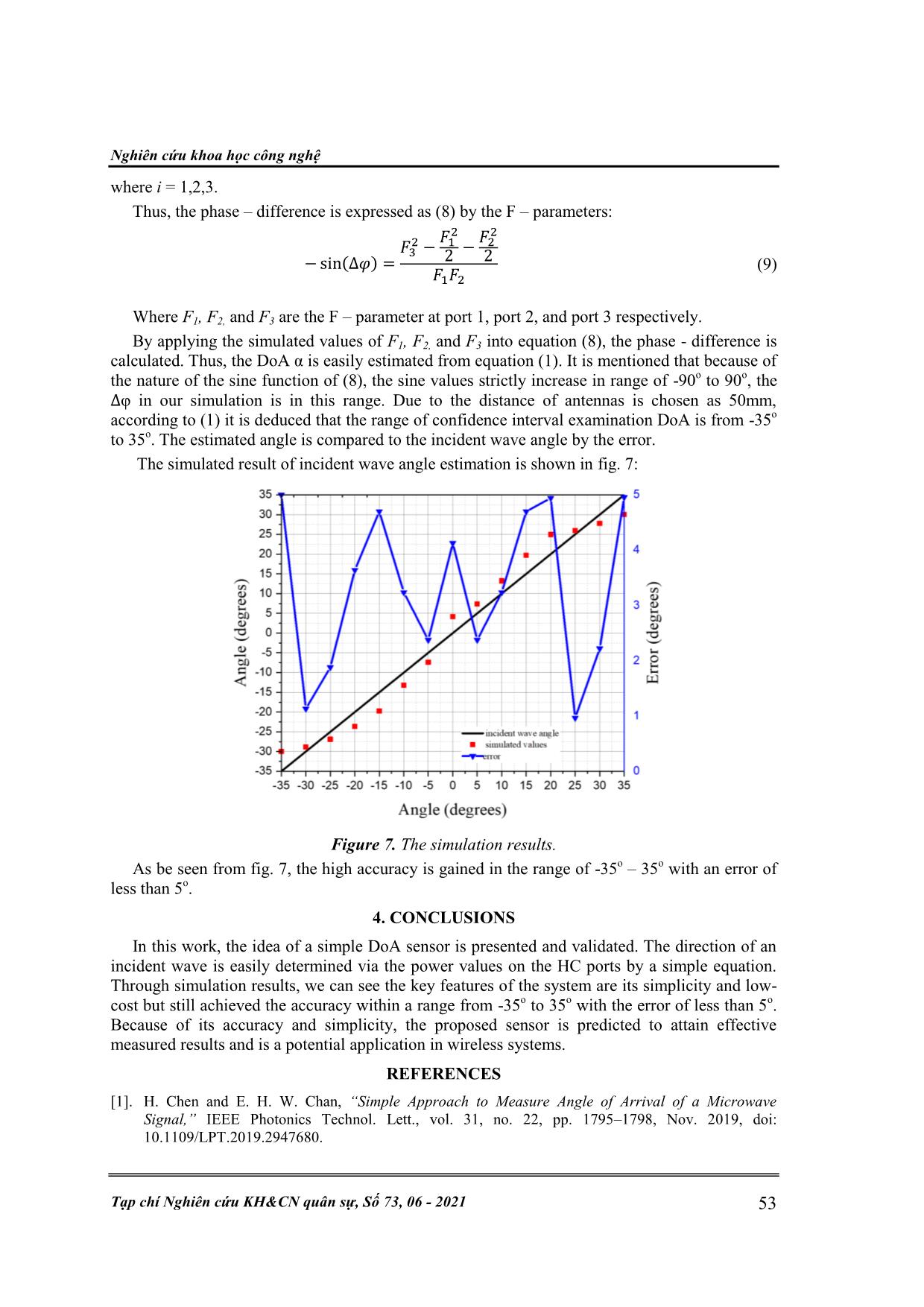
 The simulated result of incident wave angle estimation is shown in fig. 7:
Figure 7. The simulation results.
As be seen from fig. 7, the high accuracy is gained in the range of -35
o
 – 35o with an error of
less than 5
o
.
4. CONCLUSIONS
In this work, the idea of a simple DoA sensor is presented and validated. The direction of an
incident wave is easily determined via the power values on the HC ports by a simple equation.
Through simulation results, we can see the key features of the system are its simplicity and low-
cost but still achieved the accuracy within a range from -35
o
 to 35
o
 with the error of less than 5
o
.
Because of its accuracy and simplicity, the proposed sensor is predicted to attain effective
measured results and is a potential application in wireless systems.
REFERENCES
[1]. H. Chen and E. H. W. Chan, “Simple Approach to Measure Angle of Arrival of a Microwave
Signal,” IEEE Photonics Technol. Lett., vol. 31, no. 22, pp. 1795–1798, Nov. 2019, doi:
10.1109/LPT.2019.2947680.
Kỹ thuật điều khiển & Điện tử
 54 V. T. Nga, L. M. Thuy, “A simple power - based Direction of Arrival sensor.”
[2]. B. Mnasri, P. Burasa, S. Tatu, and K. Wu, “Interferometer based Direction-Of-Arrival Detection
System,” in 2018 18th International Symposium on Antenna Technology and Applied
Electromagnetics (ANTEM), Aug. 2018, pp. 1–3. doi: 10.1109/ANTEM.2018.8573013.
[3]. F. Yan, M. Jin, and X. Qiao, “Low-Complexity DOA Estimation Based on Compressed MUSIC and
Its Performance Analysis,” IEEE Trans. Signal Process., vol. 61, no. 8, pp. 1915–1930, Apr. 2013,
doi: 10.1109/TSP.2013.2243442.
[4]. F. Akbari, S. Shirvani Moghaddam, and V. Tabataba Vakili, “MUSIC and MVDR DOA estimation
algorithms with higher resolution and accuracy,” in 2010 5th International Symposium on
Telecommunications, Tehran, Iran, Dec. 2010, pp. 76–81. doi: 10.1109/ISTEL.2010.5734002.
[5]. T. B. Lavate, V. K. Kokate, and A. M. Sapkal, “Performance Analysis of MUSIC and ESPRIT DOA
Estimation Algorithms for Adaptive Array Smart Antenna in Mobile Communication,” in 2010
Second International Conference on Computer and Network Technology, Apr. 2010, pp. 308–311.
doi: 10.1109/ICCNT.2010.45.
TÓM TẮT
CẢM BIẾN HƯỚNG SÓNG TỚI DỰA TRÊN CÔNG SUẤT THU
Trong bài báo này, chúng tôi đề xuất một cảm biến đơn giản giúp xác định hướng sóng
tới ở dải tần 2.6 GHz dựa trên các giá trị công suất thu. So với các thuật toán phức tạp
được ứng dụng rộng rãi trong các hệ thống xác định hướng sóng tới hiện nay, cảm biến
này có cấu trúc đơn giản và chỉ dựa trên công suất thu được từ bộ chia nguồn. Điều này
dẫn đến sự đơn giản hơn trong việc xử lý để xác định hướng sóng tới. Hệ thống cảm biến
hướng sóng tới đề xuất bao gồm 2 anten thu và 3 mạch hybrid coupler. Dải góc mô phỏng
thực hiện trong khoảng từ 0o – 35o với sai số nhỏ hơn 5o.
Từ khóa: Xác định hướng sóng tới; Mạch hybrid coupler.
Received May 5
th
 2021
Revised May 27
th
 2021
Published June 10
th
2021
Author affiliations:
1
School of Electrical Engineering, Hanoi University of Science and Technology.
*
Corresponding author: thuy.leminh@hust.edu.vn.
File đính kèm:
 a_simple_power_based_direction_of_arrival_sensor.pdf

