Thiết kế và lắp đặt hệ thống đo dao dộng rung trong hầm gió
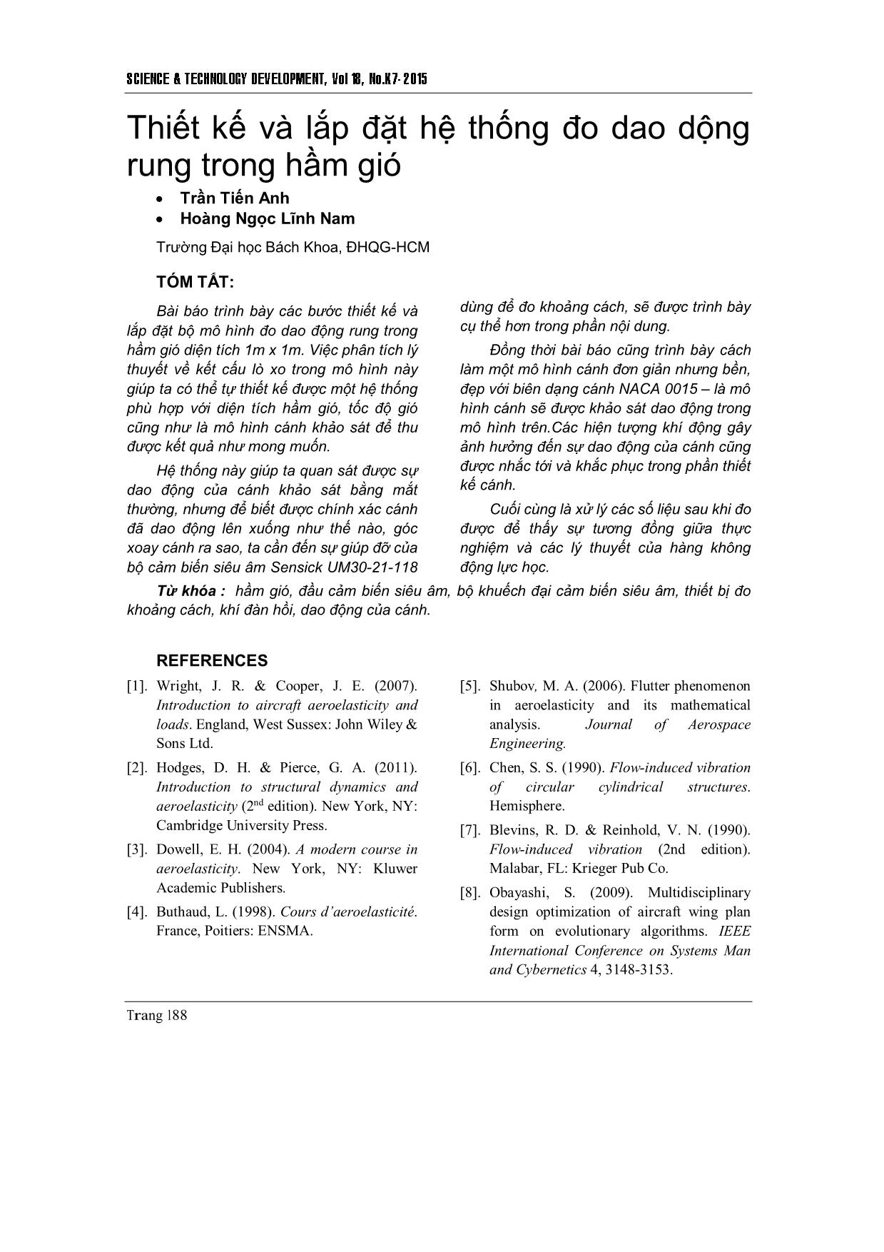
Bài báo trình bày các bước thiết kế và lắp đặt bộ mô hình đo dao động rung trong hầm gió diện tích 1m x 1m. Việc phân tích lý thuyết về kết cấu lò xo trong mô hình này giúp ta có thể tự thiết kế được một hệ thống phù hợp với diện tích hầm gió, tốc độ gió cũng như là mô hình cánh khảo sát để thu được kết quả như mong muốn. Hệ thống này giúp ta quan sát được sự dao động của cánh khảo sát bằng mắt thường, nhưng để biết được chính xác cánh đã dao động lên xuống như thế nào, góc xoay cánh ra sao, ta cần đến sự giúp đỡ của bộ cảm biến siêu âm Sensick UM30-21-118
Trang 1
Trang 2
Trang 3
Trang 4
Trang 5
Trang 6
Trang 7
Trang 8
Trang 9
Bạn đang xem tài liệu "Thiết kế và lắp đặt hệ thống đo dao dộng rung trong hầm gió", để tải tài liệu gốc về máy hãy click vào nút Download ở trên
Tóm tắt nội dung tài liệu: Thiết kế và lắp đặt hệ thống đo dao dộng rung trong hầm gió
SCIENCE & TECHNOLOGY DEVELOPMENT, Vol 18, No.K7- 2015
Trang 188
Thiết kế và lắp đặt hệ thống đo dao dộng
rung trong hầm gió
 Trần Tiến Anh
 Hoàng Ngọc Lĩnh Nam
Trường Đại học Bách Khoa, ĐHQG-HCM
TÓM TẮT:
Bài báo trình bày các bước thiết kế và
lắp đặt bộ mô hình đo dao động rung trong
hầm gió diện tích 1m x 1m. Việc phân tích lý
thuyết về kết cấu lò xo trong mô hình này
giúp ta có thể tự thiết kế được một hệ thống
phù hợp với diện tích hầm gió, tốc độ gió
cũng như là mô hình cánh khảo sát để thu
được kết quả như mong muốn.
Hệ thống này giúp ta quan sát được sự
dao động của cánh khảo sát bằng mắt
thường, nhưng để biết được chính xác cánh
đã dao động lên xuống như thế nào, góc
xoay cánh ra sao, ta cần đến sự giúp đỡ của
bộ cảm biến siêu âm Sensick UM30-21-118
dùng để đo khoảng cách, sẽ được trình bày
cụ thể hơn trong phần nội dung.
Đồng thời bài báo cũng trình bày cách
làm một mô hình cánh đơn giản nhưng bền,
đẹp với biên dạng cánh NACA 0015 – là mô
hình cánh sẽ được khảo sát dao động trong
mô hình trên.Các hiện tượng khí động gây
ảnh hưởng đến sự dao động của cánh cũng
được nhắc tới và khắc phục trong phần thiết
kế cánh.
Cuối cùng là xử lý các số liệu sau khi đo
được để thấy sự tương đồng giữa thực
nghiệm và các lý thuyết của hàng không
động lực học.
Từ khóa : hầm gió, đầu cảm biến siêu âm, bộ khuếch đại cảm biến siêu âm, thiết bị đo
khoảng cách, khí đàn hồi, dao động của cánh.
REFERENCES
[1]. Wright, J. R. & Cooper, J. E. (2007).
Introduction to aircraft aeroelasticity and
loads. England, West Sussex: John Wiley &
Sons Ltd.
[2]. Hodges, D. H. & Pierce, G. A. (2011).
Introduction to structural dynamics and
aeroelasticity (2nd edition). New York, NY:
Cambridge University Press.
[3]. Dowell, E. H. (2004). A modern course in
aeroelasticity. New York, NY: Kluwer
Academic Publishers.
[4]. Buthaud, L. (1998). Cours d’aeroelasticité.
France, Poitiers: ENSMA.
[5]. Shubov, M. A. (2006). Flutter phenomenon
in aeroelasticity and its mathematical
analysis. Journal of Aerospace
Engineering.
[6]. Chen, S. S. (1990). Flow-induced vibration
of circular cylindrical structures.
Hemisphere.
[7]. Blevins, R. D. & Reinhold, V. N. (1990).
Flow-induced vibration (2nd edition).
Malabar, FL: Krieger Pub Co.
[8]. Obayashi, S. (2009). Multidisciplinary
design optimization of aircraft wing plan
form on evolutionary algorithms. IEEE
International Conference on Systems Man
and Cybernetics 4, 3148-3153.
TAÏP CHÍ PHAÙT TRIEÅN KH&CN, TAÄP 18, SOÁ K7- 2015
 Trang 189
Toward wave-body interaction roblems
using CIP method: A demonstrating 2
phase problem
 Tran Tien Anh
 Bui Quan Hung
Ho Chi Minh city University of Technology, VNU-HCM
(Manuscript Received on July 08th, 2015, Manuscript Revised September 23rd, 2015)
ABSTRACT:
CIP (constrained interpolation profile) is
one of the CFD (computational fluid
dynamics) methods developed by Japanese
professor Takashi Yabe. It is used to
simulate 3 phase problems including air on
the surface, liquid and structure in solid form.
To check the validity of CIP theory,
experiments with different problems have
been implemented and obtained very
positive results. This proves the correctness
of the CIP method.
Based on the need of simulation of wave
structure interaction (water wave with float of
seaplanes, wing in ground effect crafts,
piers, drilling, casing ships...), this paper
applies the theory of CIP method to find the
answer to the problem of 2D simulation via a
obstacle. Objectives to do are understanding
the physics, finding out the differential
equations describing the phenomenon, then
proceeding discrete, setting up algorithms
and finding out solution of the equations.
This paper uses Matlab software to write
programs and displays the results.
Key words: numerical algorithm, constrained interpolation profile, free surface problem,
fluid structure interaction, multiphase flows, governing equations.
1. INTRODUCTION
1.1.Objectives
It is very important to know interaction of
water waves on structures (body and float of
seaplanes, flying boats, piers, drilling, casing
ships...). The main objective of this paper is to
establish a numerical prediction way for how
water waves impact to a solid body.
Purpose of this paper includes constructing
algorithms and computational simulation
modules, calculating the fluid forces acting on
the structure (lift, drag, torque) and processing
and displaying calculated results.
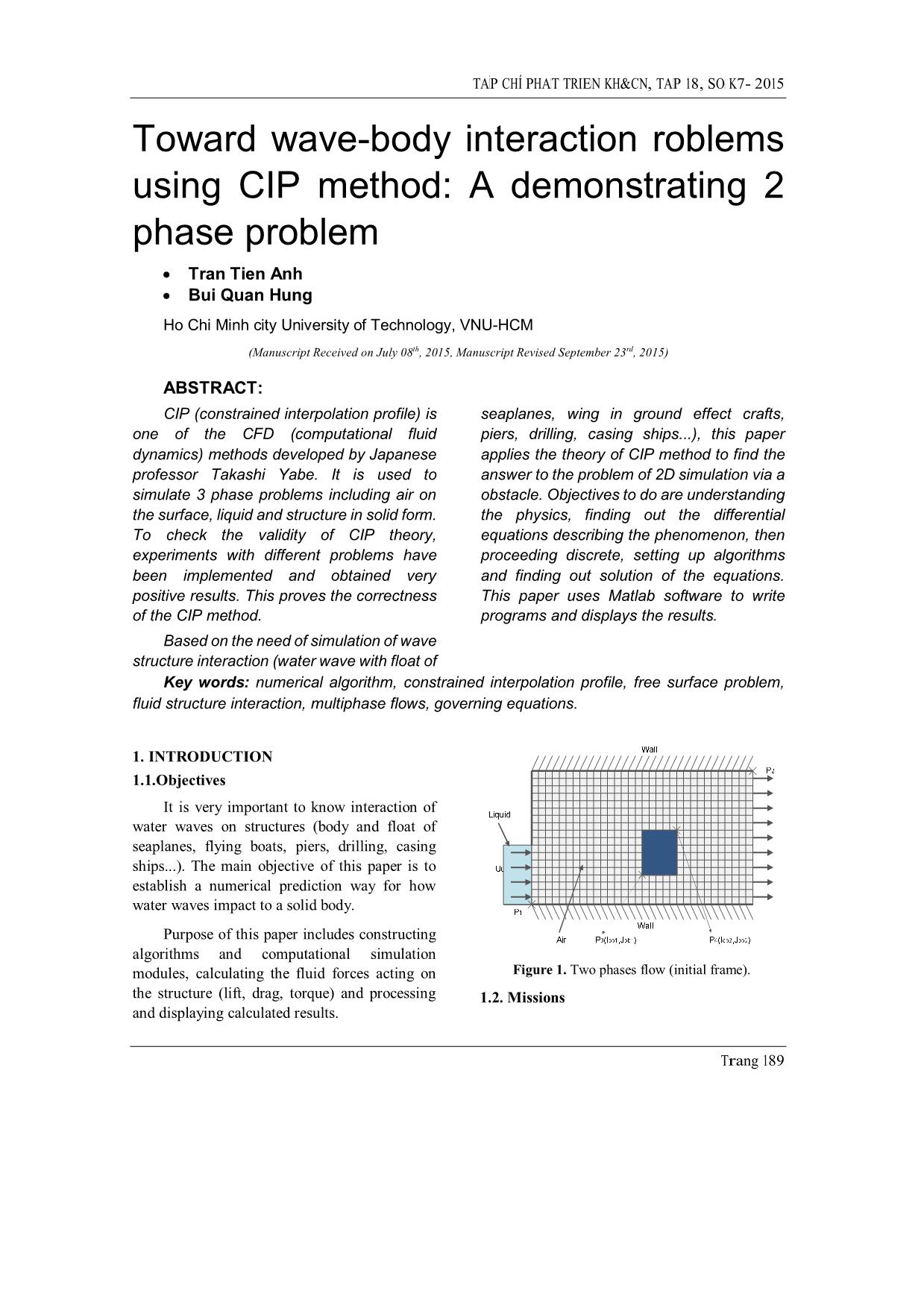
Figure 1. Two phases flow (initial frame).
1.2. Missions
SCIENCE & TECHNOLOGY DEVELOPMENT, Vol 18, No.K7- 2015
Trang 190
CIP is a CFD method developed by a
Japanese professor [1]. CIP is used to simulate 3-
phase environments consisting of air over the
surface, liquid and a structure. The problem can
be understood simply as follows:
- Using equations to des
File đính kèm:
 thiet_ke_va_lap_dat_he_thong_do_dao_dong_rung_trong_ham_gio.pdf

