Kinematic and dynamic analysis of a serial manipulator with local closed loop mechanisms
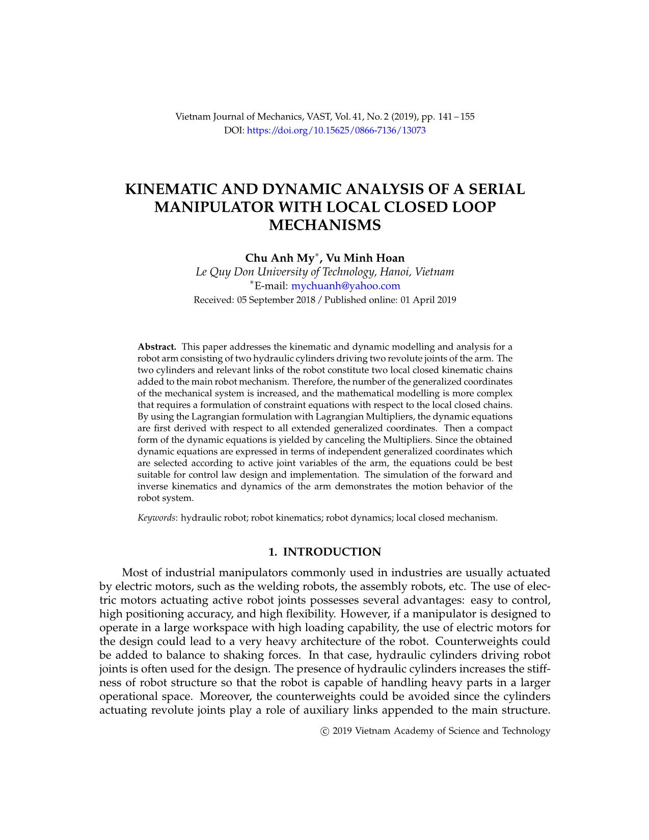
Abstract. This paper addresses the kinematic and dynamic modelling and analysis for a
robot arm consisting of two hydraulic cylinders driving two revolute joints of the arm. The
two cylinders and relevant links of the robot constitute two local closed kinematic chains
added to the main robot mechanism. Therefore, the number of the generalized coordinates
of the mechanical system is increased, and the mathematical modelling is more complex
that requires a formulation of constraint equations with respect to the local closed chains.
By using the Lagrangian formulation with Lagrangian Multipliers, the dynamic equations
are first derived with respect to all extended generalized coordinates. Then a compact
form of the dynamic equations is yielded by canceling the Multipliers. Since the obtained
dynamic equations are expressed in terms of independent generalized coordinates which
are selected according to active joint variables of the arm, the equations could be best
suitable for control law design and implementation. The simulation of the forward and
inverse kinematics and dynamics of the arm demonstrates the motion behavior of the
robot system.
Trang 1
Trang 2
Trang 3
Trang 4
Trang 5
Trang 6
Trang 7
Trang 8
Trang 9
Trang 10
Tải về để xem bản đầy đủ
Tóm tắt nội dung tài liệu: Kinematic and dynamic analysis of a serial manipulator with local closed loop mechanisms
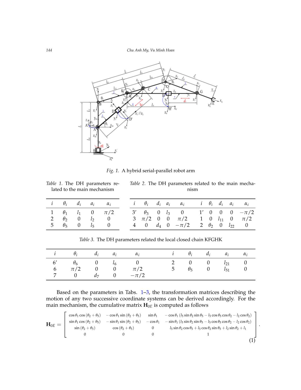
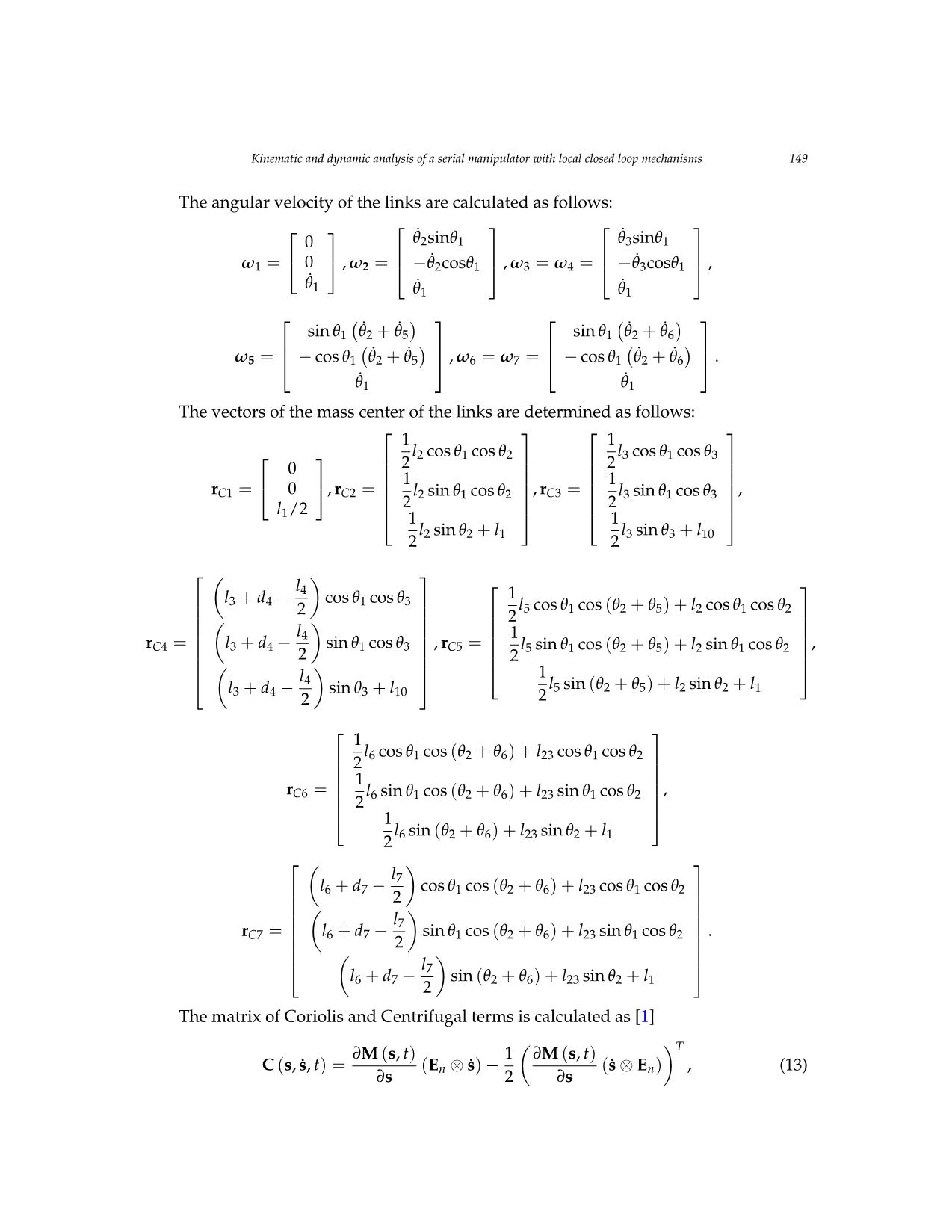
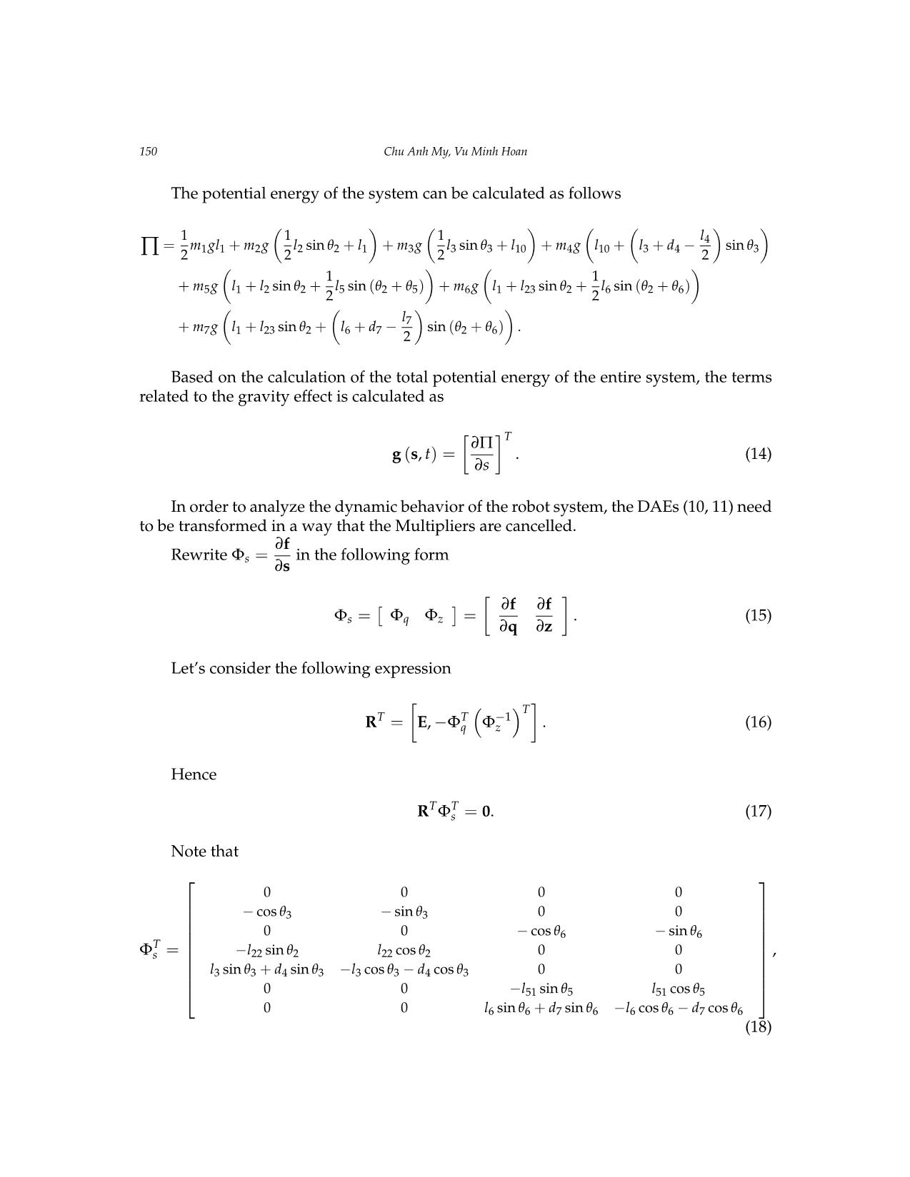
Vietnam Journal of Mechanics, VAST, Vol. 41, No. 2 (2019), pp. 141 – 155 DOI: https://doi.org/10.15625/0866-7136/13073 KINEMATIC AND DYNAMIC ANALYSIS OF A SERIAL MANIPULATOR WITH LOCAL CLOSED LOOP MECHANISMS Chu Anh My∗, Vu Minh Hoan Le Quy Don University of Technology, Hanoi, Vietnam ∗E-mail: mychuanh@yahoo.com Received: 05 September 2018 / Published online: 01 April 2019 Abstract. This paper addresses the kinematic and dynamic modelling and analysis for a robot arm consisting of two hydraulic cylinders driving two revolute joints of the arm. The two cylinders and relevant links of the robot constitute two local closed kinematic chains added to the main robot mechanism. Therefore, the number of the generalized coordinates of the mechanical system is increased, and the mathematical modelling is more complex that requires a formulation of constraint equations with respect to the local closed chains. By using the Lagrangian formulation with Lagrangian Multipliers, the dynamic equations are first derived with respect to all extended generalized coordinates. Then a compact form of the dynamic equations is yielded by canceling the Multipliers. Since the obtained dynamic equations are expressed in terms of independent generalized coordinates which are selected according to active joint variables of the arm, the equations could be best suitable for control law design and implementation. The simulation of the forward and inverse kinematics and dynamics of the arm demonstrates the motion behavior of the robot system. Keywords: hydraulic robot; robot kinematics; robot dynamics; local closed mechanism. 1. INTRODUCTION Most of industrial manipulators commonly used in industries are usually actuated by electric motors, such as the welding robots, the assembly robots, etc. The use of elec- tric motors actuating active robot joints possesses several advantages: easy to control, high positioning accuracy, and high flexibility. However, if a manipulator is designed to operate in a large workspace with high loading capability, the use of electric motors for the design could lead to a very heavy architecture of the robot. Counterweights could be added to balance to shaking forces. In that case, hydraulic cylinders driving robot joints is often used for the design. The presence of hydraulic cylinders increases the stiff- ness of robot structure so that the robot is capable of handling heavy parts in a larger operational space. Moreover, the counterweights could be avoided since the cylinders actuating revolute joints play a role of auxiliary links appended to the main structure. c© 2019 Vietnam Academy of Science and Technology 142 Chu Anh My, Vu Minh Hoan Though there will be advantages when using hydraulic cylinders for robot designs, the presence of cylinders in a robot architecture involves complex procedures for the math- ematical modelling, analysis and control. The addition of cylinders to the conventional serial kinematic chain of robot arm architecture could constitute local closed kinematic chains within the entire robot mechanism. Issues related to the hybrid serial–parallel fea- ture of the robot structure, the geometry, the mass and the inertia of cylinders must be taken into account. In the literature, numerous works have been carried out to investigate several as- pects related to the dynamic modeling and analysis of serial manipulators and paral- lel robots [1–21]. The fundamentals of kinematic and dynamic modelling and analysis of serial manipulators can be found in [1, 2], where Denavit-Hartenberg approach was mostly used for the kinematic modelling and D’Alembert–Lagrange Formulation for the dynamic modelling. As for more complex robotic systems, there has been a number of researches dealing with different issues related to the kinematics and the dynamics as well. The research presented in [3] studied the kinematic and dynamic modelling for closed chain manipulators, [4] addressed algorithms for the dynamic analysis of serial robots having a large number of joints, [5] investigated the inverse kinematics and dy- namics of the redundant robots, [6] studied the dynamics of mobile serial manipulators. In parallel with researches concerning with the serial robot dynamics, a massive number of researches related to the dynamics and control of parallel robots has been addressed as well such as publications [7–21]. The researches [8,10,13] investigated methods for the inverse and forward dynamic modelling and analysis of the 3-PRS type parallel manipu- lators. The Screw theory was used in [9], and the matrix approach was employed in [11] for the dynamics and control of the parallel robots. A general solution to the problem of dynamic modelling and analysis of parallel robots was presented in [12]. For the issue of control law design and development, [14] investigated a model-based technique, [15–17] addressed the robust control algorithms, whereas the s ... havior of the robot system, the DAEs (10, 11) need to be transformed in a way that the Multipliers are cancelled. Rewrite Φs = ∂f ∂s in the following form Φs = [ Φq Φz ] = [ ∂f ∂q ∂f ∂z ] . (15) Let’s consider the following expression RT = [ E,−ΦTq ( Φ−1z )T] . (16) Hence RTΦTs = 0. (17) Note that ΦTs = 0 0 0 0 − cos θ3 − sin θ3 0 0 0 0 − cos θ6 − sin θ6 −l22 sin θ2 l22 cos θ2 0 0 l3 sin θ3 + d4 sin θ3 −l3 cos θ3 − d4 cos θ3 0 0 0 0 −l51 sin θ5 l51 cos θ5 0 0 l6 sin θ6 + d7 sin θ6 −l6 cos θ6 − d7 cos θ6 , (18) Kinematic and dynamic analysis of a serial manipulator with local closed loop mechanisms 151 R = 1 0 0 0 1 0 0 0 1 0 − 1 l22 sin (θ2 − θ3) 0 0 − cos (θ2 − θ3) (d4 + l3) sin (θ2 − θ3) 0 0 0 1 l51 sin (θ6 − θ5) 0 0 cos (θ6 − θ5) (d7 + l6) sin (θ6 − θ5) , (19) s˙ = Rq˙, (20) s¨ = Rq¨+ R˙q˙. (21) Substituting (17), (20), (21) into (10) yields M¯q¨+ C¯q˙+ G¯q = τq, (22) where M¯ = RTM (s, t)R, C¯ = RT ( M (s, t) R˙+C (s, s˙, t)R ) , G¯ = RTg (s, t) , and τq = RTτ (t). Eq. (22) is expressed in term of independent generalized coordinates, q = [θ1d4d7] T. Notice that all the formulations above are implemented and demonstrated in Maple envi- ronment. The following section shows the numeric solutions of the forward and inverse dynamic issues. 3.1. Forward dynamics simulation The dynamical parameters of the robot system are given in Tab. 4 Table 4. The parameters of the robot Link Center of gravity Mass Inertia xC yC zC Ixx Iyy Izz Ixy Iyz Izx 1 0 lC1 0 m1 I1x I1y I1z 0 0 0 2 lC2 0 0 m2 I2x I2y I2z 0 0 0 3 0 0 lC3 m3 I3x I3y I3z 0 0 0 4 0 lC4 0 m4 I4x I4y I4z 0 0 0 5 lC5 0 0 m5 I5x I5y I5z 0 0 0 6 0 0 lC6 m6 I6x I6y I6z 0 0 0 7 0 lC7 0 m7 I7x I7y I7z 0 0 0 l1 = 0.7 m; l10 = 0.4 m; l11 = 0.3 m; l2 = 0.6 m; l20 = 0.2 m; l21 = 0.4 m; l22 = 0.4 m; l23 = 0.2 m; l3 = 0.4 m; l4 = 0.4 m; l5 = 1.2 m; l51 = 0.8 m; l52 = 0.4 m; l6 = 0.4 m; l7 = 0.4 m. 152 Chu Anh My, Vu Minh Hoan We assume that lC1 = l1/2 = 0.35 m; lC2 = l2/2 = 0.3 m; lC3 = l3/2 = 0.2 m; lC5 = l5/2 = 0.6 m; lC6 = l6/2 = 0.2 m; lC4 = l4/2 = 0.2 m; lC7 = l7/2 = 0.2 m; −5pi6 ≤ θ1 ≤ 5pi 6 ; 0.1 ≤ d4 < l4; 0.1 ≤ d7 < l7, m1 = 80 kg; m2 = 60 kg; m3 = 20 kg; m4 = 10 kg; m5 = 50 kg; m6 = 20 kg; m7 = 10 kg. I1x = m1l21/12; I1z = m1l 2 1/12; I2x = 0; I2y = m2l 2 2/12; I2z = m2l 2 2/12; I3x = m3l 2 3/12; I3y = m3l23/12; I3z = 0; I4x = m4l 2 4/12; I4y = 0; I4z = m4l 2 4/12; I5x = 0; I5y = m5l 2 5/12; I5z = m5l25/12; I6x = m6l 2 6/12; I6y = m6l 2 6/12; I6z = 0; I7x = m7l 2 7/12; I7y = 0; I7z = m7l 2 7/12. The applied torque/forces are given as τ1 (t) = 1.5× sin (2t) , F4 (t) = 50 (20+ t) , F7 (t) = 30 (20− t) . Fig. 9 shows the time evolution of θ1 (t), d4 (t) and d7 (t). 0 0.02 0.04 0.06 0.08 0.1 0.12 0.14 0.16 0.18 0.2 times [s] 0 0.05 0.1 0.15 0.2 0.25 0.3 0.35 0.4 teta1 d4 d7 Fig. 9. The time evolution of θ1 (t), d4 (t) and d7 (t) 3.2. Inverse dynamics simulation To demonstrate the inverse dynamic analysis, two cases of simulation are consid- ered. The inputs of the simulation are given as θ1 (t) = pi × t 18 , d4(t) = 0.1+ 0.005× t, and d7(t) = 0.1+ 0.02× t. For the first case, the mass of the link 3, 4, 6 and 7 equals to zero. In the second case, the mass of the link 3, 4, 6 and 7 are given as m3 = 20 kg, m4 = 10 kg, m6 = 20 kg and m7 = 10 kg. Figs. 10–12 show the results of the inverse dynamic analysis. The “black” curves are the time evolution of the computed torque/forces corresponding to the first case, while the “gray” ones are for the second case. Kinematic and dynamic analysis of a serial manipulator with local closed loop mechanisms 153 0 5 10 15 times [s] -0.02 -0.018 -0.016 -0.014 -0.012 -0.01 -0.008 -0.006 M1 1 M1 2 Fig. 10. τ1(t) Kinematic and dynamic analysis of a serial manipulator with local closed loop mechanisms 13 Fig 9. The time evolution of 1 t , 4d t and 7d t Inverse dynamics simulation To demonstrate the inverse dynamic analysis, two cases of simulation are considered. The inputs of the simulation are given as 1 18 t t , 4 ( ) 0.1 0.005d t t , and 7 ( ) 0.1 0.02d t t . For the first case, the mass of the link 3, 4, 6 and 7 equals to zero. In the second case, the mass of the link 3, 4, 6 and 7 are given as 3m =20 kg, 4m =10 kg, 6m =20 kg and 7 m =10 kg. Figs 10, 11 and 12 show the results of the inverse dynamic analysis. The “red” curves are the time evolution of the computed torque/forces corresponding to the first case, while the “green” ones are for the second case. Fig 10. 1( )t Fig 11. 4( )F t 0 0.02 0.04 0.06 0.08 0.1 0.12 0.14 0.16 0.18 0.2 times [s] 0 0.05 0.1 0.15 0.2 0.25 0.3 0.35 0.4 teta1 d4 d7 0 5 10 15 times [s] - . - . - . - . - . - . - . -0.006 M1 1 M1 2 0 5 10 15 times [s] 900 1000 1100 1200 1300 1400 1500 1600 1700 1800 1900 F 4 [ N ] F4 1 F4 2 Fig. 11. F4(t) My Anh Chu, Hoan Minh Vu 14 Fig 12. 4( )F t It can be seen that there is a considerable change of the computed torque/forces when considering the mass of the hydraulic cylinders in the dynamic model of the robot system. 4. CONCLUSION The kinematic and dynamic equations for a particular type of robot have been formulated. It has shown that when the mass and inertia of a hydraulic cylinder driving a revolution joint of a robot are considered, such the cylinder and relevant links of the robot constitute a local closed mechanism appended to the main robot architecture. By taking into account this particular feature of the hydraulic robot, the kinematic and dynamic modelling and analysis of the robot are more accurate. This could help to design more efficient and more effective control laws for the arm. Acknowledgment: This research is funded by Vietnam National Foundation for Science and Technology Development (NAFOSTED) under grant number 107.04-2017.09. REFERENCES [1] Nguyen V Khang, and Chu A My. Fundamentals of industrial robots, Text Book. Vietnam Education Publisher, 2011 (in Vietnamese). [2] Craig J J. Introduction to Robotics: Mechanics and Control, 3rd Edn., Pearson Education, Upper Saddle River, NJ, USA, 2005. [3] Murray J and Lovell G. Dynamic modeling of closed-chain robotic manipulators and implications for trajectory control. IEEE T. Robotic. Autom. 1989; 5: 522–528. [4] Mata V, Provenzano S, Valero F and Cuadrado J I. Serialrobot dynamics algorithms for moderately large numbers of joints. Mech. Mach. Theory. 2002; 37: 739–755. [5] Tran H N. Inverse kinematic, dynamics and sliding mode control of redundant manipulator. PhD thesis. Institute of Mechanics, Vietnam Academy of Science and Technology. 2010 (In Vietnamese) [6] Chu A My, et al. Mechanical design and dynamics modelling of RoPC robot. Proceedings of International Symposium on Robotics and Mechatronics, Hanoi, Vietnam. Sept 2009; 92-96. [7] Merlet J P. Parallel robots. London Kluwer Academic Publishers, 2000. 0 5 10 15 times [s] 400 500 600 700 800 900 1000 1100 F7 1 F7 2 Fig. 12. F7(t) It can be seen that there is a considerable change of the computed torque/forces when considering the mass of the hydraulic cylinders in the dynamic model of the robot system. 4. CONCLUSION The kinematic and dynamic equations for a particular type of robot have been for- mulated. It has shown that when the mass and inertia of a hydraulic cylinder driving a revolution joint of a robot are considered, such the cylinder and relevant links of the robot constitute a local closed mechanism appended to the main robot architecture. By taking i to account this particular featur of the hyd aulic robot, the kinematic and dy- namic modelling and analysis of the robot are more accurate. This could help to design more efficient and more effective control laws for the arm. 154 Chu Anh My, Vu Minh Hoan ACKNOWLEDGMENT This research is funded by Vietnam National Foundation for Science and Technology Development (NAFOSTED) under grant number 107.04-2017.09. REFERENCES [1] N. V. Khang and C. A. My. Fundamentals of industrial robots. Vietnam Education Publisher, (2011). (n Vietnamese). [2] J. J. Craig. Introduction to robotics: Mechanics and control. Pearson Education, Upper Saddle River, NJ, USA, (2005). [3] J. J. Murray and G. H. Lovell. Dynamic modeling of closed-chain robotic manipulators and implications for trajectory control. IEEE Transactions on Robotics and Automation, 5, (4), (1989), pp. 522–528. https://doi.org/10.1109/70.88066. [4] V. Mata, S. Provenzano, F. Valero, and J. I. Cuadrado. Serial-robot dynamics algorithms for moderately large numbers of joints. Mechanism and machine Theory, 37, (8), (2002), pp. 739– 755. https://doi.org/10.1016/s0094-114x(02)00030-7. [5] H. N. Tran. Inverse kinematic, dynamics and sliding mode control of redundant manipulator. PhD thesis, Institute of Mechanics, Vietnam Academy of Science and Technology, (2010). (In Viet- namese). [6] C. A. My. Mechanical design and dynamics modelling of RoPC robot. In Proceedings of Inter- national Symposium on Robotics and Mechatronics, Hanoi, Vietnam, (2009). pp. 92–96. [7] J. P. Merlet. Parallel robots. London Kluwer Academic Publishers, (2000). [8] O. Ibrahim and W. Khalil. Kinematic and dynamic modeling of the 3-PRS parallel manipu- lator. In Proceedings of the 12th IFToMMWorld congress, France, (2007). pp. 1–6. [9] L. Carbonari, M. Battistelli, M. Callegari, and M. C. Palpacelli. Dynamic modelling of a 3-CPU parallel robot via screw theory. Mechanical Sciences, 4, (1), (2013), pp. 185–197. https://doi.org/10.5194/ms-4-185-2013. [10] Y. Li and Q. Xu. Kinematics and inverse dynamics analysis for a gen- eral 3-PRS spatial parallel mechanism. Robotica, 23, (2), (2005), pp. 219–229. https://doi.org/10.1017/s0263574704000797. [11] S. Staicu. Matrix modeling of inverse dynamics of spatial and planar parallel robots. Multi- body System Dynamics, 27, (2), (2012), pp. 239–265. https://doi.org/10.1007/s11044-011-9281- 8. [12] W. Khalil and O. Ibrahim. General solution for the dynamic modeling of parallel robots. Jour- nal of Intelligent and Robotic Systems, 49, (1), (2007), pp. 19–37. https://doi.org/10.1007/s10846- 007-9137-x. [13] W. H. Yuan and M. S. Tsai. A novel approach for forward dynamic analysis of 3-PRS parallel manipulator with consideration of friction effect. Robotics and Computer-Integrated Manufac- turing, 30, (3), (2014), pp. 315–325. https://doi.org/10.1016/j.rcim.2013.10.009. [14] M. Diaz-Rodriguez, A. Valera, V. Mata, and M. Valles. Model-based control of a 3-DOF par- allel robot based on identified relevant parameters. IEEE/ASME Transactions on Mechatronics, 18, (6), (2012), pp. 1737–1744. https://doi.org/10.1109/tmech.2012.2212716. [15] D. H. Kim, J. Y. Kang, and K. I. Lee. Nonlinear robust control design for a 6 DOF parallel robot. KSME International Journal, 13, (7), (1999), pp. 557–568. https://doi.org/10.1007/BF03186446. Kinematic and dynamic analysis of a serial manipulator with local closed loop mechanisms 155 [16] K. Fu and J. K. Mills. Robust control design for a planar parallel robot. In- ternational Journal of Robotics & Automation, 22, (2), (2007), pp. 139–147. https://doi.org/10.2316/journal.206.2007.2.206-2937. [17] Y. Li and Q. Xu. Dynamic modeling and robust control of a 3-PRC translational parallel kinematic machine. Robotics and Computer-Integrated Manufacturing, 25, (3), (2009), pp. 630– 640. https://doi.org/10.1016/j.rcim.2008.05.006. [18] H. B. Guo, Y. G. Liu, G. R. Liu, and H. R. Li. Cascade control of a hydraulically driven 6- DOF parallel robot manipulator based on a sliding mode. Control Engineering Practice, 16, (9), (2008), pp. 1055–1068. https://doi.org/10.1016/j.conengprac.2007.11.005. [19] A. Codourey. Dynamic modeling of parallel robots for computed-torque control imple- mentation. The International Journal of Robotics Research, 17, (12), (1998), pp. 1325–1336. https://doi.org/10.1177/027836499801701205. [20] H. Abdellatif and B. Heimann. Advanced model-based control of a 6-DOF hexapod ro- bot: A case study. IEEE/ASME Transactions On Mechatronics, 15, (2), (2009), pp. 269–279. https://doi.org/10.1109/tmech.2009.2024682. [21] Q. Li and F. X. Wu. Control performance improvement of a parallel robot via the design for control approach. Mechatronics, 14, (8), (2004), pp. 947–964. https://doi.org/10.1016/j.mechatronics.2004.04.002. [22] O. Ibrahim and W. Khalil. Inverse and direct dynamic models of hy- brid robots. Mechanism and Machine Theory, 45, (4), (2010), pp. 627–640. https://doi.org/10.1016/j.mechmachtheory.2009.11.007. [23] D. Pisla, A. Szilaghyi, C. Vaida, and N. Plitea. Kinematics and workspace modeling of a new hybrid robot used in minimally invasive surgery. Robotics and Computer-Integrated Manufac- turing, 29, (2), (2013), pp. 463–474. https://doi.org/10.1016/j.rcim.2012.09.016. [24] T. K. Tanev. Kinematics of a hybrid (parallel–serial) robot manipulator. Mechanism and Ma- chine Theory, 35, (9), (2000), pp. 1183–1196. https://doi.org/10.1016/s0094-114x(99)00073-7. [25] P. Xu, C. F. Cheung, B. Li, L. T. Ho, and J. F. Zhang. Kinematics analysis of a hybrid ma- nipulator for computer controlled ultra-precision freeform polishing. Robotics and Computer- Integrated Manufacturing, 44, (2017), pp. 44–56. https://doi.org/10.1016/j.rcim.2016.08.003. [26] Q. Zeng and Y. Fang. Structural synthesis and analysis of serial–parallel hybrid mechanisms with spatial multi-loop kinematic chains. Mechanism and Machine Theory, 49, (2012), pp. 198– 215. https://doi.org/10.1016/j.mechmachtheory.2011.10.008. [27] Q. Zeng and K. F. Ehmann. Design of parallel hybrid-loop manipulators with kinema- totropic property and deployability. Mechanism and Machine Theory, 71, (2014), pp. 1–26. https://doi.org/10.1016/j.mechmachtheory.2013.08.017. [28] D. Zhang and Z. Gao. Performance analysis and optimization of a five-degrees-of-freedom compliant hybrid parallel micromanipulator. Robotics and Computer-Integrated Manufacturing, 34, (2015), pp. 20–29. https://doi.org/10.1016/j.rcim.2015.01.002. [29] C. A. My. Inverse kinematics of a serial-parallel robot used in hot forging process. Vietnam Journal of Mechanics, 38, (2), (2016), pp. 81–88. https://doi.org/10.15625/0866- 7136/38/2/5958. [30] C. A. My, C. H. Le, M. Packianather, and E. L. J. Bohez. Novel robot arm design and im- plementation for hot forging press automation. International Journal of Production Research, (2018), pp. 1–15. https://doi.org/10.1080/00207543.2018.1521026. [31] N. V. Khang, N. P. Dien, N. V. Vinh, and T. H. Nam. Inverse kinematic and dynamic analysis of redundant measuring manipulator BKHN-MCX-04. Vietnam Journal of Mechanics, 32, (1), (2010), pp. 15–26. https://doi.org/10.15625/0866-7136/32/1/313.
File đính kèm:
 kinematic_and_dynamic_analysis_of_a_serial_manipulator_with.pdf

