Hệ thống định vị và điều hướng trong nhà
Hệ thống định vị và điều hướng trong nhà đã và đang có nhu cầu ngày càng tăng với phát
triển của công nghệ điện thoại thông minh. Tuy nhiên cho tới thời điểm hiện tại hầu như chưa có một hệ
thống tiêu chuẩn nào đặt ra cho các hệ thống điều hướng trong nhà. Các hệ thống điều hướng trong nhà có
nhiều tác dụng, có thể kể đến như điều hướng hỗ trợ cho 7.3 triệu công dân khiếm thị ở Mỹ. Xét trên quy
mô toàn thế giới thì các hệ thống điều hướng kiểu này còn có tiềm năng lớn hơn rất nhiều lần. Do điểm
yếu của công nghệ GPS và tín hiệu không dây trong nhà nên vấn đề định vị và theo dõi trong nhà đã được
chứng minh là vấn đề khó khăn hơn so với điều kiện ngoài trời. Các phương pháp tiếp cận hiện nay đã và
đang sử dụng hướng tiếp cập bằng các kỹ thuật như mô hình xác thực vân tay kết hợp tần số vô tuyến để
định vị. Trong bài báo này chúng tôi đề xuất hệ thống BluNavi, một hệ thống điều hướng trong nhà hiệu
quả và có thể triển khai rộng rãi. Hệ thống bao gồm hai mô đun chính là: lấy dấu vân tay Wi-Fi và Bộ lọc
Kalman mở rộng dựa trên tín hiệu báo hiệu năng lượng thấp của bluetooth. Mỗi mô-đun được đánh giá
độ chính xác riêng của nó. Hệ thống lấy dấu vân tay đạt độ chính xác trung bình là 82,33% ± 3,07% với
độ tin cậy 95%. Mô hình tính toán góc chết đã thu được độ chính xác trung bình là 3,88m ± 0,37m với độ
tin cậy 95%. Mô hình lan truyền có độ chính xác 5,91m± 1,61m với độ tin cậy 95%. Bộ lọc Kalman mở
rộng với sử dụng cảm biến có độ chính xác 10,22m ± 0,91m với độ tin cậy 95 %.
Trang 1
Trang 2
Trang 3
Trang 4
Trang 5
Trang 6
Trang 7
Trang 8
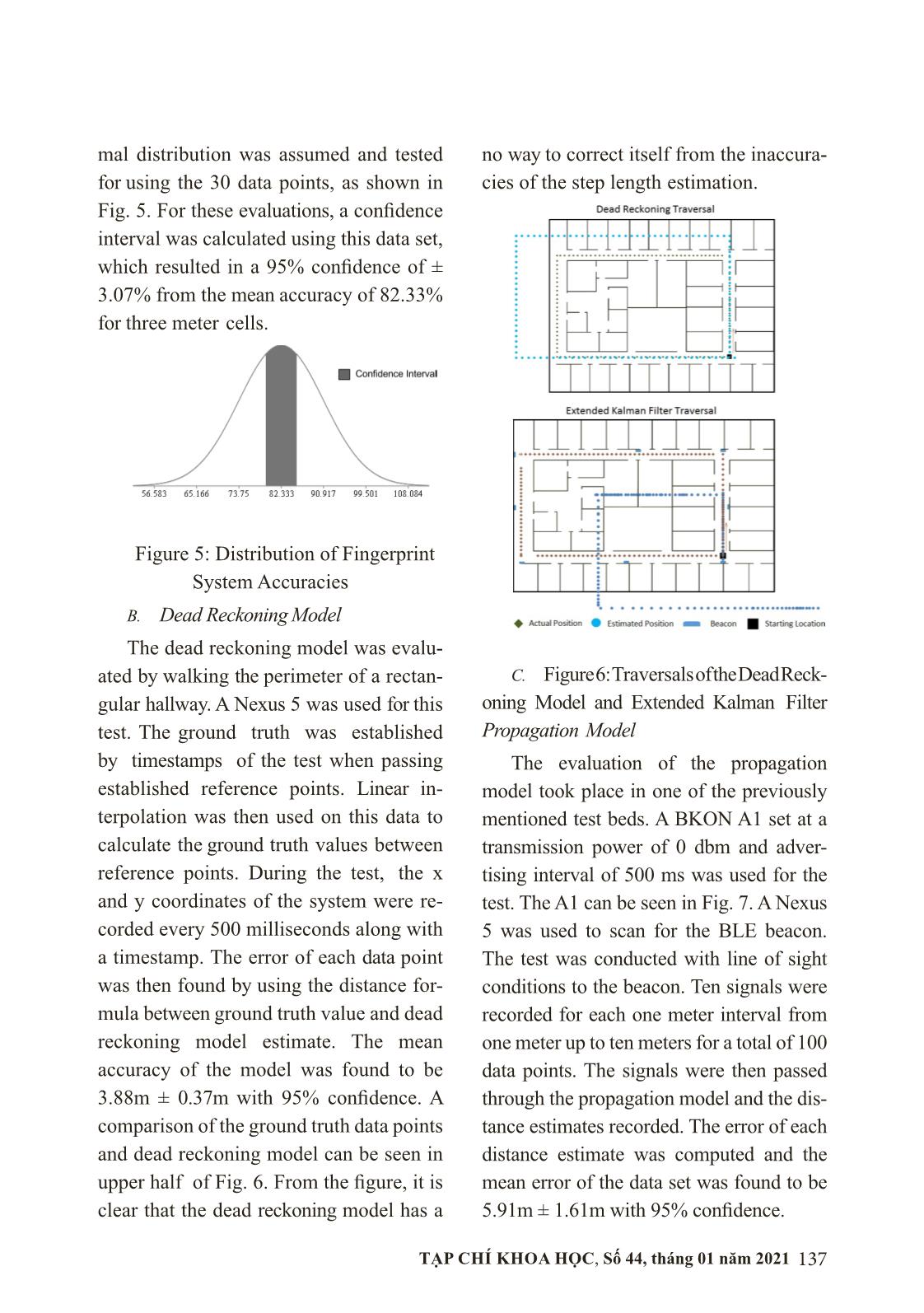
Trang 9
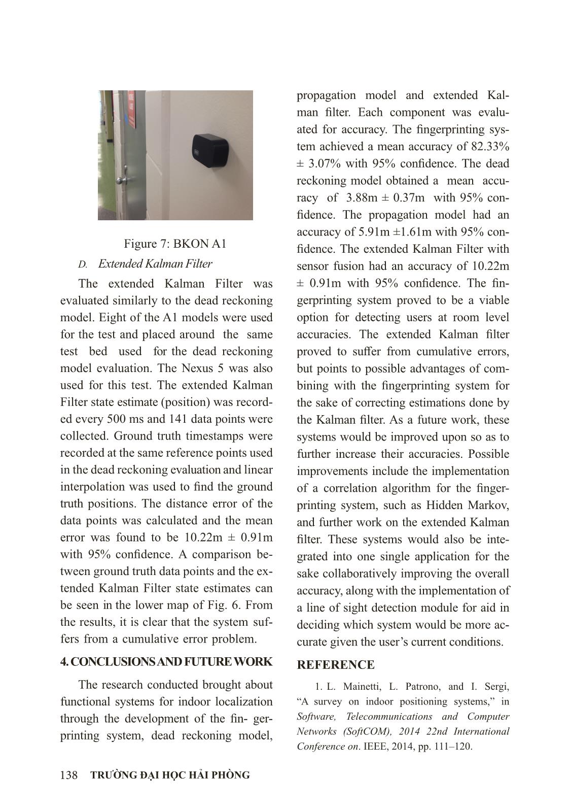
Trang 10
Tải về để xem bản đầy đủ
Tóm tắt nội dung tài liệu: Hệ thống định vị và điều hướng trong nhà
129TẠP CHÍ KHOA HỌC, Số 44, tháng 01 năm 2021
BLUNAVI: AN INDOOR POSITIONING AND NAVIGATION SYSTEM
Nguyễn Ngọc Khương
Khoa Công nghệ thông tin
Email: khuongnn@dhhp.edu.vn
Ngày nhận bài: 15/6/2020
Ngày PB đánh giá: 12/9/2020
Ngày duyệt đăng: 25/9/2020
ABSTRACT: Indoor navigation systems have been in in- creasing demand since the introduction of
smartphone technology; however, no standard system for indoor nav- igation has been established. An indoor
navigation has many applications, for example, to help the 7.3 million visually impaired citizens in the US
to navigate indoors. Due to the weaknesses of GPS and wireless signals indoors, the problem of localizing
and tracking has proven to be difficult. Current approaches have utilized techniques such as fingerprinting
and radio frequency propagation models for localization. This paper proposes BluNavi, a cost- efficient and
widely deployable indoor navigation system. BluNavi implements and compares two modules: Wi-Fi fin-
gerprinting and an extended Kalman Filter based on dead reckoning and bluetooth low energy beacon signals.
Each module was evaluated for its accuracy. The fingerprinting system achieved a mean accuracy of 82.33%
± 3.07% with 95% confidence. The dead reckoning model obtained a mean accuracy of 3.88m ± 0.37m
with 95% confidence. The propagation model had an accuracy of 5.91m ± 1.61m with 95% confidence. The
extended Kalman Filter with sensor fusion had an accuracy of 10.22m ± 0.91m with 95% confidence.
Keywords: Indoor navigation, BLE, Wi- Fifingerprinting, dead reckoning, propagation model, Kalman Filter
HỆ THỐNG ĐỊNH VỊ VÀ ĐIỀU HƯỚNG TRONG NHÀ
TÓM TẮT: Hệ thống định vị và điều hướng trong nhà đã và đang có nhu cầu ngày càng tăng với phát
triển của công nghệ điện thoại thông minh. Tuy nhiên cho tới thời điểm hiện tại hầu như chưa có một hệ
thống tiêu chuẩn nào đặt ra cho các hệ thống điều hướng trong nhà. Các hệ thống điều hướng trong nhà có
nhiều tác dụng, có thể kể đến như điều hướng hỗ trợ cho 7.3 triệu công dân khiếm thị ở Mỹ. Xét trên quy
mô toàn thế giới thì các hệ thống điều hướng kiểu này còn có tiềm năng lớn hơn rất nhiều lần. Do điểm
yếu của công nghệ GPS và tín hiệu không dây trong nhà nên vấn đề định vị và theo dõi trong nhà đã được
chứng minh là vấn đề khó khăn hơn so với điều kiện ngoài trời. Các phương pháp tiếp cận hiện nay đã và
đang sử dụng hướng tiếp cập bằng các kỹ thuật như mô hình xác thực vân tay kết hợp tần số vô tuyến để
định vị. Trong bài báo này chúng tôi đề xuất hệ thống BluNavi, một hệ thống điều hướng trong nhà hiệu
quả và có thể triển khai rộng rãi. Hệ thống bao gồm hai mô đun chính là: lấy dấu vân tay Wi-Fi và Bộ lọc
Kalman mở rộng dựa trên tín hiệu báo hiệu năng lượng thấp của bluetooth. Mỗi mô-đun được đánh giá
độ chính xác riêng của nó. Hệ thống lấy dấu vân tay đạt độ chính xác trung bình là 82,33% ± 3,07% với
độ tin cậy 95%. Mô hình tính toán góc chết đã thu được độ chính xác trung bình là 3,88m ± 0,37m với độ
tin cậy 95%. Mô hình lan truyền có độ chính xác 5,91m± 1,61m với độ tin cậy 95%. Bộ lọc Kalman mở
rộng với sử dụng cảm biến có độ chính xác 10,22m ± 0,91m với độ tin cậy 95 %.
Từ khóa: Điều hướng trong nhà, BLE, Wi-Fi, Mô hình lan truyền ngược, Bộ lọc Kalman
±
130 TRƯỜNG ĐẠI HỌC HẢI PHÒNG
I. INTRODUCTION
Indoor navigation systems have been in
increasing demand since the introduction
of smartphone technology. The sensors in
smartphones can be used to provide accu-
rate localization in an outdoor environ-
ment by using the Global Positioning Sys-
tem, but so far, no standard indoor localiza-
tion system has been implemented due to
inaccuracy and cost.
The problem with such a system per-
tains to localizing and tracking the user in
an indoor space. This problem has many
challenges that must be solved. Mainetti,
et al. [1] lists some of these challenges,
including: the loss of signal precision of
wireless systems due to Non-Line-of-Sight
(NLOS) conditions and multipath effect,
scaling the system for large spaces, and
complex environments.
A practical, accurate and cost-efficient
indoor navigation system that solves these
challenges has many beneficial ap- plica-
tions such as assisting firemen to navigate
a burning, smoke-filled building, locating
people in danger in emergency situations,
and navigation of public spaces such as
malls, airports, and university buildings.
One important but unconsidered appli-
cation of an indoor navigation system is as-
sistance for the visually impaired. In 2013,
there was a reported 7.3 million people in
the United States with some form of visual
impairment [2]. With no form of eletronic
navigation assistance when in an indoor
setting, these individuals are hindered when
traversing public spaces, such as malls, uni-
versities, airports and bus or train stations,
among others. This means that these indi-
viduals need some form of help to find t ... n
scan for access points;
for i = 0 to N do
 for each ref. point containing the AP do
 if |RSS
IAP
 – RSS
IDB
| <= X then
 increase weight of location;
 end
 end
end
return highest weight location;
Algorithm 2: Estimating User Location.
Variable X is a threshold due to how RSSI values vary.
A. Fingerprinting
134 TRƯỜNG ĐẠI HỌC HẢI PHÒNG
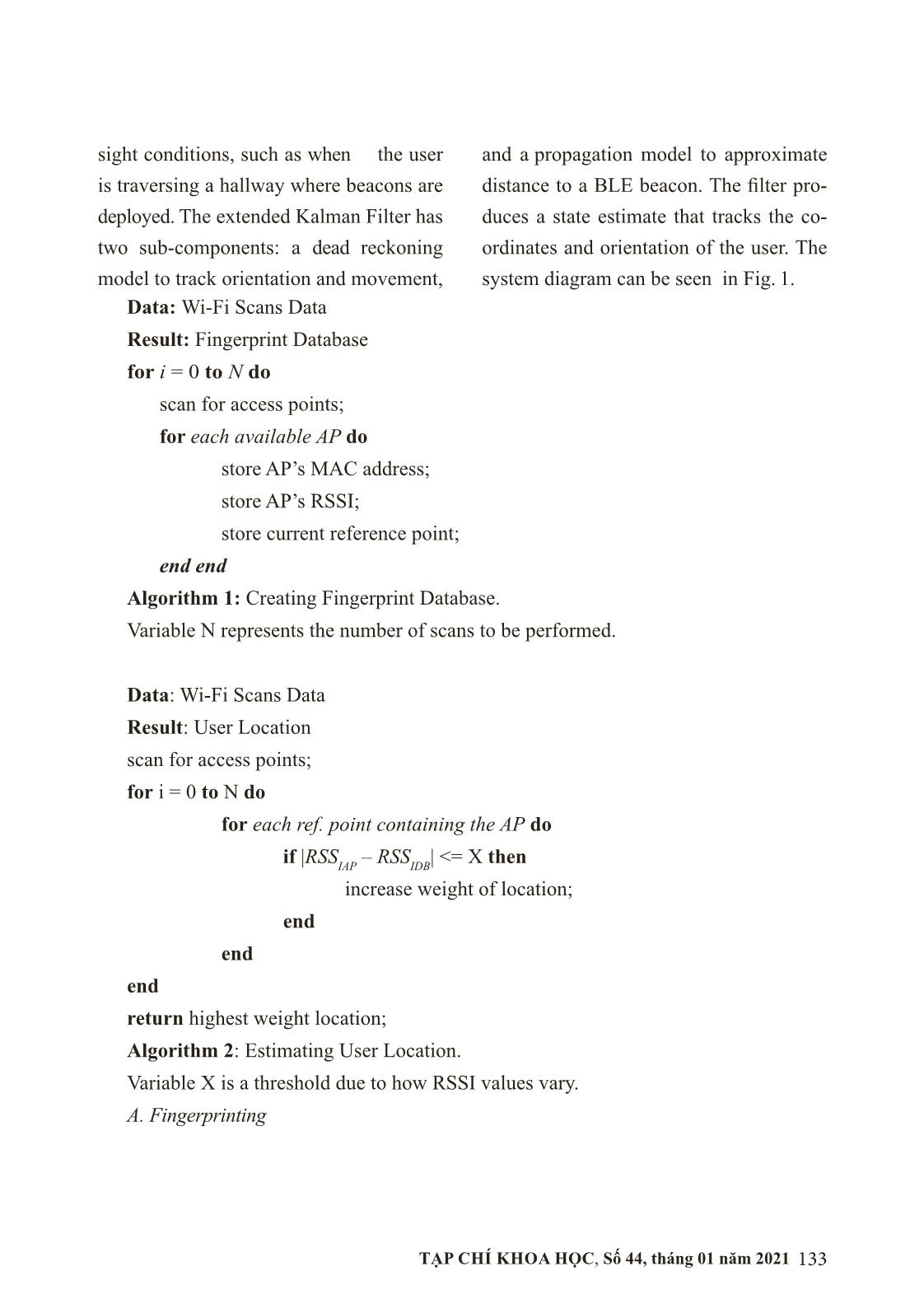
Figure 1: System Diagram
The Wi-Fi Fingerprinting module will
be used when NLOS conditions are de-
tected from all available beacons, or when
no beacons are in range of detection. To
implement fingerprinting, a map with ref-
erence points needs to be created. At every
reference point, RSSI data for every avail-
able access point needs to be collected.
The system makes use of the algorithm
presented below to scan reference points
with a device.
After this database is created, the
system can estimate the user’s location
through a weight based approach, where
a weight is assigned to each reference
point based on the similarities between the
user’s current scans and the finger- print
database. This is done through the algo-
rithm shown on algorithm 2.
 B. Pedestrian Dead Reckoning Model
BluNavi uses a dead reckoning model
to track two key local-ization components:
orientation and displacement (movement).
Displacement occurs when the user of the
system takes a step. Changes in orienta-
tion result from the user turning to face
a new direction. The IMU’s available in
most mobile devices are used to track both
components. A gyroscope is used to track
changes in orientation.
Displacement of the user is estimated
by calculating the length of the user’s cur-
rent walk step. For this purpose, BluNavi’s
dead reckoning model uses measurements
provided by an accelerometer to calculate
step length. The data is passed through a
low-pass filter to remove noise and smooth
the curve. The filtered values are then
used in a formula derived from the one
used by Bao, et al. [14]. The equation can
be seen in Eq. 1.
( ) 418n fh al ch vll a a a a= − −
 (1)
where n is the current step, l
n
 is the
length of step n, a
fh
 and a
fl
 are the high
(maximum) and low (mimimum) values
of the accelerometers forward accelera-
tion axis during step n, respectively, and
a
vh
 and a
vl
 are the high and low values of
the accelerometer’s vertical axis during
135TẠP CHÍ KHOA HỌC, Số 44, tháng 01 năm 2021
step n, respectively. K is a constant that
expresses the leg length of the user and is
determined through training.
Two methods can be used to determine
when a step has been completed. If a step
detector is available in the mobile device,
then the data provided from it is used for
step detection. Otherwise, a step detec-
tion process begins when the vertical ac-
celeration values pass a set threshold. The
threshold is used to avoid recording a false
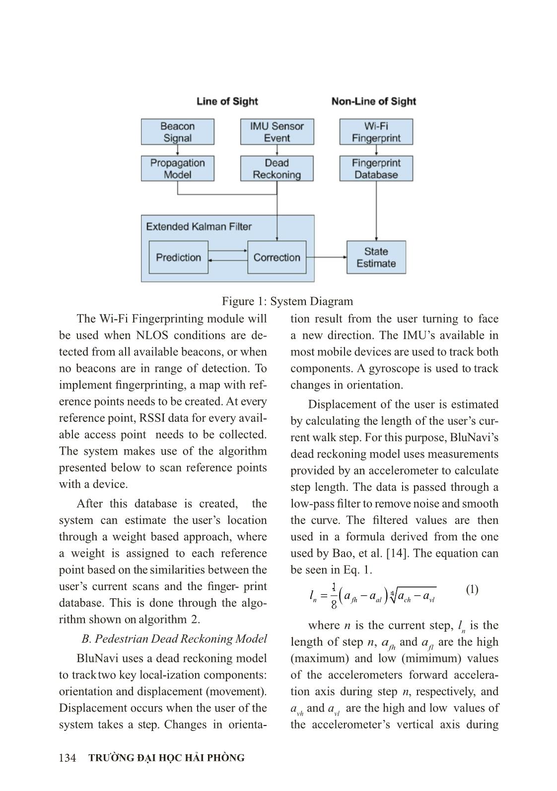
peak during the begining of a step. Fig. 2
demonstrates a threshold on accelerometer
data that was collected from a test where
ten steps were taken. The peak is record-
ed when the partial derivative of the data
changes from positive to negative. Then,
the lowest value is recorded. When the next
peak is detected, the process is over and the
step length is calculated using equation 1.
Figure 2: Vertical Acceleration Data
C. Propagation Model
For indoor localization, distance from
device to beacon is approximated using a
radio frequency propagation model. Blu-
Navi uses the log-distance path loss model
as described by Zhuang, et al [13]. The
model can be seen in Eq. 2
0 10( ) ( ) 10 log ( )P d P d d Xσγ= − + (2)
where P (d) represents the RSS at dis-
tance d, P (d
0
) is the transmission power,
γ is the path-loss exponent, and X
σ
 is a
Gaussian random variable with zero mean
and standard deviation of 4.11 found from
experimental analysis of BLE beacon sig-
nal strength. The model has acceptable ac-
curacy in open, line of sight environments
but suffers when used in enclosed places.
For this reason, an extended Kalman Filter
is used to increase the accuracy.
D. Extended Kalman Filter
The extended Kalman Filter (EKF) is
used in BluNavi to increase the localiza-
tion accuracy of the system by fusing sen-
sor data provided by the dead reckoning
model and the propagation model. The
filter works in two steps: a prediction step
and a correction step.
The prediction step predicts the cur-
rent state and the error of the prediction
using a standard Kalman Filter process
model and process covariance model. The
process model estimates movement (or
non-movement) through the indoor envi-
ronment. The model is given by Eq. 3.
1kp k kx Ax Bu−= + (3)
where x
kp
 is the predicted state
vector at time k, A is the state tran-
sition matrix, x
k−1
 is the previous state
vector, B is the control input transition
matrix, and u
k
 is the control input vec-
tor. Control input will be step length esti-
mations provided by the dead reckoning
model. The state vector is defined as:
[ ]Tx X Y= (4)
136 TRƯỜNG ĐẠI HỌC HẢI PHÒNG
the process covariance model is de-
fined as: 1
T
kp k kP AP A Q−= + (5)
where P
kp
 is the predicted process
covariance matrix and Q
k
 is the process
noise covariance matrix.
Next, after a BLE beacon signal is de-
tected, the propagation model feeds in the
distance estimate into the measurement
model of the filter, which is as follows:
k k k kz H x v= + (6)
where z
k
 is the measurement vector,
H
k
 is the measurement transition matrix
and vK is zero-mean, Gaussian white-noise
caused by errors in the sensors.
The next step is to update the state
vector and process covariance matrix
based on the process and measurement
models. The models for this step can be
defined as follows:
( ) 1T Tk kp k k kp kK P H H P H R
−
= + (7)
( )k kp k k k kpx x K z H x= + − (8)
( )k k k kpP I K H K= − (9)
where K
k
 is the kalman gain, R is
the measurement noise covariance
matrix dervied from v
k
, x
k
 is the
corrected current state estimate, and I is
the identity matrix.
3. EVALUATION
Experimental analysis was conducted
in order to evaluate the accuracy of the
proposed system. Multiple test beds were
created in the hallways of the University of
South Florida ENB II building. One meter
cells were established in each of the hall-
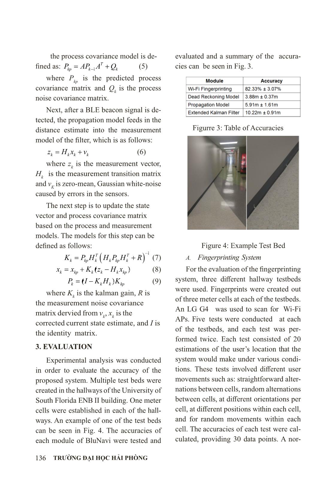
ways. An example of one of the test beds
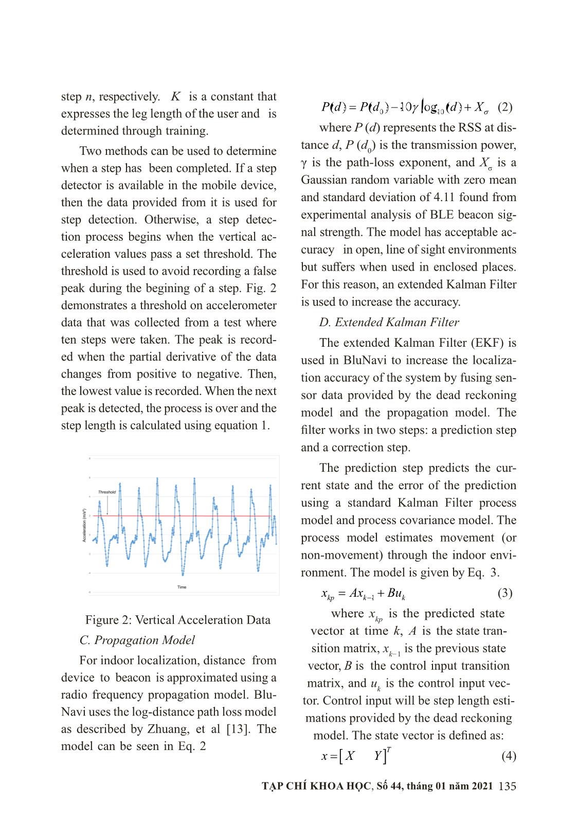
can be seen in Fig. 4. The accuracies of
each module of BluNavi were tested and
evaluated and a summary of the accura-
cies can be seen in Fig. 3.
Figurre 3: Table of Accuracies
Figure 4: Example Test Bed
A. Fingerprinting System
For the evaluation of the fingerprinting
system, three diff erent hallway testbeds
were used. Fingerprints were created out
of three meter cells at each of the testbeds.
An LG G4 was used to scan for Wi-Fi
APs. Five tests were conducted at each
of the testbeds, and each test was per-
formed twice. Each test consisted of 20
estimations of the user’s location that the
system would make under various condi-
tions. These tests involved different user
movements such as: straightforward alter-
nations between cells, random alternations
between cells, at different orientations per
cell, at different positions within each cell,
and for random movements within each
cell. The accuracies of each test were cal-
culated, providing 30 data points. A nor-
137TẠP CHÍ KHOA HỌC, Số 44, tháng 01 năm 2021
mal distribution was assumed and tested
for using the 30 data points, as shown in
Fig. 5. For these evaluations, a confidence
interval was calculated using this data set,
which resulted in a 95% confidence of ±
3.07% from the mean accuracy of 82.33%
for three meter cells.
Figure 5: Distribution of Fingerprint
System Accuracies
B. Dead Reckoning Model
The dead reckoning model was evalu-
ated by walking the perimeter of a rectan-
gular hallway. A Nexus 5 was used for this
test. The ground truth was established
by timestamps of the test when passing
established reference points. Linear in-
terpolation was then used on this data to
calculate the ground truth values between
reference points. During the test, the x
and y coordinates of the system were re-
corded every 500 milliseconds along with
a timestamp. The error of each data point
was then found by using the distance for-
mula between ground truth value and dead
reckoning model estimate. The mean
accuracy of the model was found to be
3.88m ± 0.37m with 95% confidence. A
comparison of the ground truth data points
and dead reckoning model can be seen in
upper half of Fig. 6. From the figure, it is
clear that the dead reckoning model has a
no way to correct itself from the inaccura-
cies of the step length estimation.
C. Figure 6: Traversals of the Dead Reck-
oning Model and Extended Kalman Filter
Propagation Model
The evaluation of the propagation
model took place in one of the previously
mentioned test beds. A BKON A1 set at a
transmission power of 0 dbm and adver-
tising interval of 500 ms was used for the
test. The A1 can be seen in Fig. 7. A Nexus
5 was used to scan for the BLE beacon.
The test was conducted with line of sight
conditions to the beacon. Ten signals were
recorded for each one meter interval from
one meter up to ten meters for a total of 100
data points. The signals were then passed
through the propagation model and the dis-
tance estimates recorded. The error of each
distance estimate was computed and the
mean error of the data set was found to be
5.91m ± 1.61m with 95% confidence.
138 TRƯỜNG ĐẠI HỌC HẢI PHÒNG
Figure 7: BKON A1
D. Extended Kalman Filter
The extended Kalman Filter was
evaluated similarly to the dead reckoning
model. Eight of the A1 models were used
for the test and placed around the same
test bed used for the dead reckoning
model evaluation. The Nexus 5 was also
used for this test. The extended Kalman
Filter state estimate (position) was record-
ed every 500 ms and 141 data points were
collected. Ground truth timestamps were
recorded at the same reference points used
in the dead reckoning evaluation and linear
interpolation was used to find the ground
truth positions. The distance error of the
data points was calculated and the mean
error was found to be 10.22m ± 0.91m
with 95% confidence. A comparison be-
tween ground truth data points and the ex-
tended Kalman Filter state estimates can
be seen in the lower map of Fig. 6. From
the results, it is clear that the system suf-
fers from a cumulative error problem.
4. CONCLUSIONS AND FUTURE WORK
The research conducted brought about
functional systems for indoor localization
through the development of the fin- ger-
printing system, dead reckoning model,
propagation model and extended Kal-
man filter. Each component was evalu-
ated for accuracy. The fingerprinting sys-
tem achieved a mean accuracy of 82.33%
± 3.07% with 95% confidence. The dead
reckoning model obtained a mean accu-
racy of 3.88m ± 0.37m with 95% con-
fidence. The propagation model had an
accuracy of 5.91m ±1.61m with 95% con-
fidence. The extended Kalman Filter with
sensor fusion had an accuracy of 10.22m
± 0.91m with 95% confidence. The fin-
gerprinting system proved to be a viable
option for detecting users at room level
accuracies. The extended Kalman filter
proved to suffer from cumulative errors,
but points to possible advantages of com-
bining with the fingerprinting system for
the sake of correcting estimations done by
the Kalman filter. As a future work, these
systems would be improved upon so as to
further increase their accuracies. Possible
improvements include the implementation
of a correlation algorithm for the finger-
printing system, such as Hidden Markov,
and further work on the extended Kalman
filter. These systems would also be inte-
grated into one single application for the
sake collaboratively improving the overall
accuracy, along with the implementation of
a line of sight detection module for aid in
deciding which system would be more ac-
curate given the user’s current conditions.
REFERENCE
1. L. Mainetti, L. Patrono, and I. Sergi,
“A survey on indoor positioning systems,” in
Software, Telecommunications and Computer
Networks (SoftCOM), 2014 22nd International
Conference on. IEEE, 2014, pp. 111–120.
139TẠP CHÍ KHOA HỌC, Số 44, tháng 01 năm 2021
2. “National Federation of the Blind blindness
statistics”, https://nfb.org/blindness-statistics, accessed:
2016-06-20.
3. V. Otsason, A. Varshavsky, A. LaMarca, and
E. De Lara, “Accurate gsm indoor localization,” in
International conference on ubiquitous computing.
Springer, 2005, pp. 141–158.
4. N. Li and B. Becerik-Gerber, “Performance-
based evaluation of rfid- based indoor location
sensing solutions for the built environment,”
Advanced Engineering Informatics, vol. 25, no. 3,
pp. 535–546, 2011.
5. J. Liu, “Survey of wireless based indoor
localization technologies,” Dept. of Science &
Engineering, Washington University, 2014.
6. A. Ward, A. Jones, and A. Hopper, “A new
location technique for the active office,” IEEE
Personal Communications, vol. 4, no. 5, pp. 42–
47, 1997.
7. C. Medina, J. C. Segura, and A. De la Torre,
“Ultrasound indoor positioning system based on a
low-power wireless sensor network providing sub-
centimeter accuracy,” Sensors, vol. 13, no. 3, pp.
3501– 3526, 2013.
8. “Google beacons eddystone format,”
https://developers.google.com/beacons/eddystone,
accessed: 2016- 05-24.
9. S. Chan and G. Sohn, “Indoor localization
using wi-fi based finger- printing and trilateration
techiques for lbs applications,” International Archives
of the Photogrammetry, Remote Sensing and Spatial
Informa- tion Sciences, vol. 38, p. 4, 2012.
10. E. Navarro, B. Peuker, and M. Quan,
“Wi-fi localization using rssi fin- gerprinting,”
Bachelor’s thesis, California Polytechnic State
University, 2010.
11. Z. Wu, E. Jedari, R. Muscedere, and R.
Rashidzadeh, “Improved particle filter based on
wlan rssi fingerprinting and smart sensors for
indoor localization,” Computer Communications,
vol. 83, pp. 64–71, 2016.
12. R. Faragher and R. Harle, “Location
fingerprinting with bluetooth low energy beacons,”
IEEE Journal on Selected Areas in Communications,
vol. 33, no. 11, pp. 2418–2428, 2015.
13. Y. Zhuang, J. Yang, Y. Li, L. Qi, and N. El-
Sheimy, “Smartphone-based indoor localization
with bluetooth low energy beacons,” Sensors, vol.
16, no. 5, p. 596, 2016.
14. H. Bao and W.-C. Wong, “An indoor dead-
reckoning algorithm with map matching,” in 2013
9th International Wireless Communications and
Mobile Computing Conference (IWCMC). IEEE,
2013, pp. 1534–1539.
File đính kèm:
 he_thong_dinh_vi_va_dieu_huong_trong_nha.pdf

