A method for capturing accuracy and pose repeatability of articulated industrial robots
Recently, industrial*robots (IRs) have been
more and more used to realize continuous operations
such as prototyping, premachining of cast parts as
well as end-machining of middle tolerance parts [1].
In addition, for repetitive tasks such as placing,
welding, and assembling, the repeatability of IRs
typically ranging from 0.03 to 0.1 mm and their
several millimeters accuracy are commonly used.
Thus, measurement approaches for accuracy and
repeatability have been used for enhancing actual
robot positioning accuracy. Lombard and Perrot [2]
have implemented an automatic method to measure
robot accuracy. The most widely applied approach is
to use theodolite systems for calibration
measurements [3]. Another high precision devices
like Coordinate Measuring Machines (CMMs) have
been widely used for industrial dimension
measurement [4]. Laser Tracking Systems (LTS) [5]
can combine the advantages of a large working space,
high accuracy and dynamic pose measurements.
However, they are high cost, and hence it is
prohibitive to calibrate and measure robot poses with
low costs. A simple approach to measure an error
along a direction by a dial gauge has been discussed
in [6]. However, this could only give accuracy for
one direction. Using three dial gauge fixture for
industrial robots has been investigated in [7,8].
Herein, we employ a general low cost method with a
simple measurement fixture using three dial gauges to
capture the robot poses for robot accuracy evaluation
and calibrations. The measurement results show the
efficiency of the method.
Trang 1
Trang 2
Trang 3
Trang 4
Trang 5
Tóm tắt nội dung tài liệu: A method for capturing accuracy and pose repeatability of articulated industrial robots
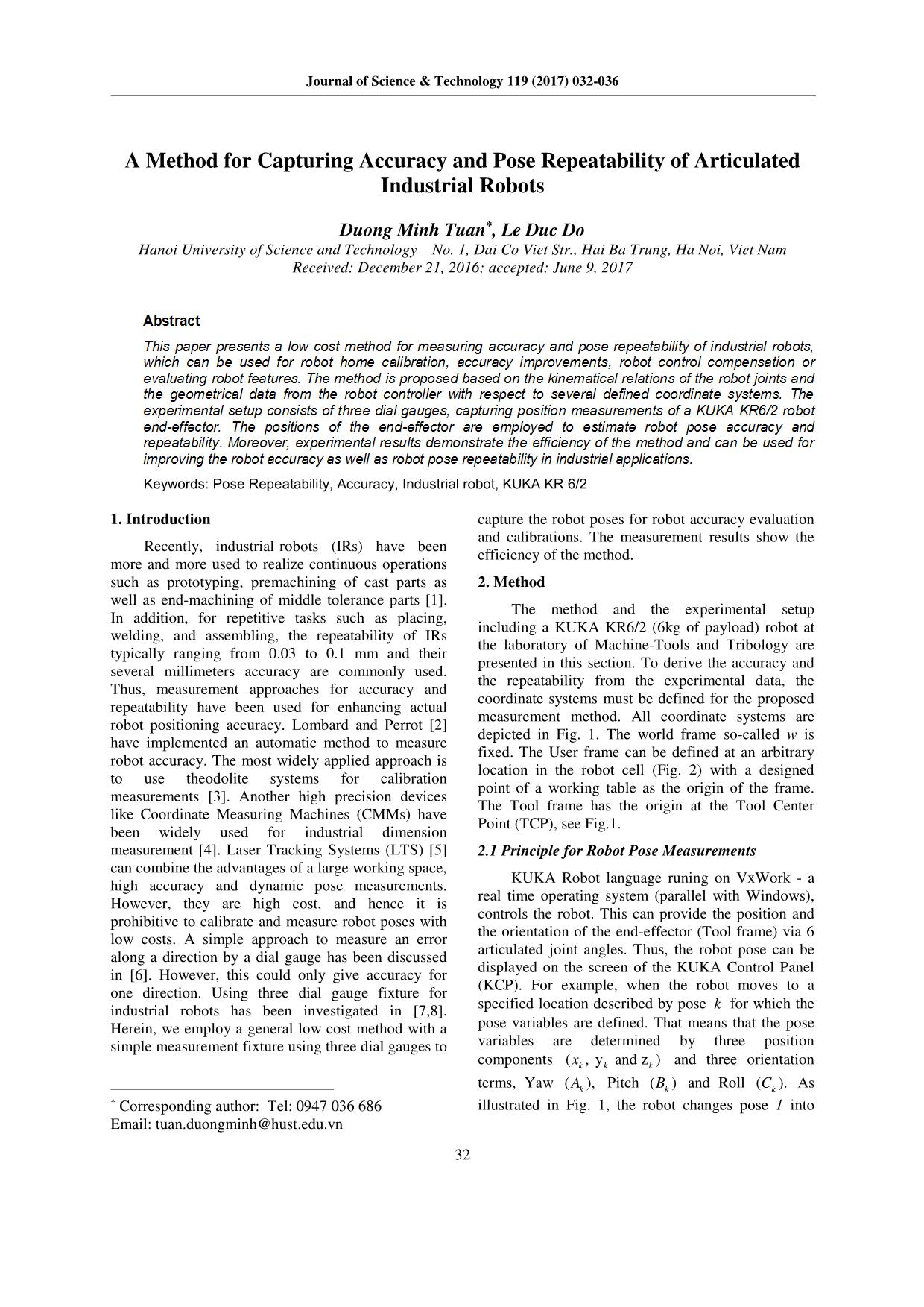
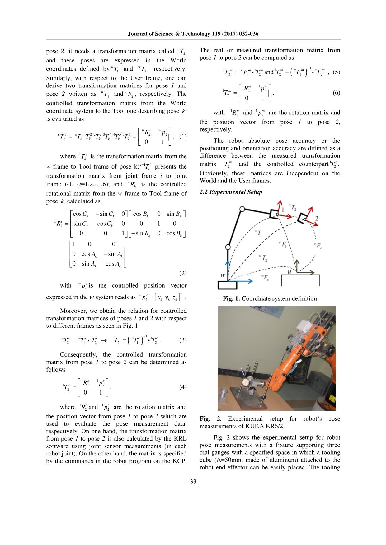
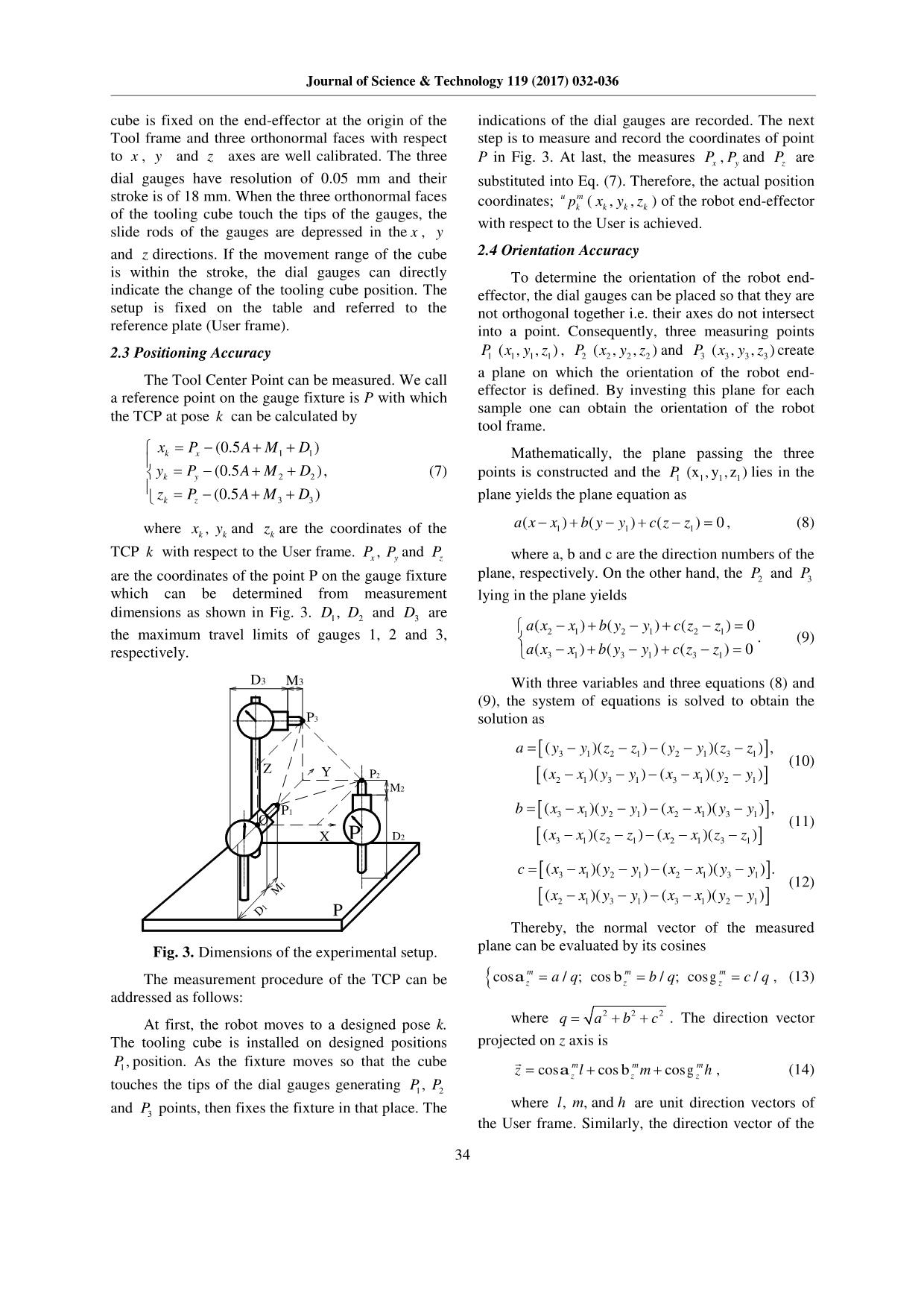
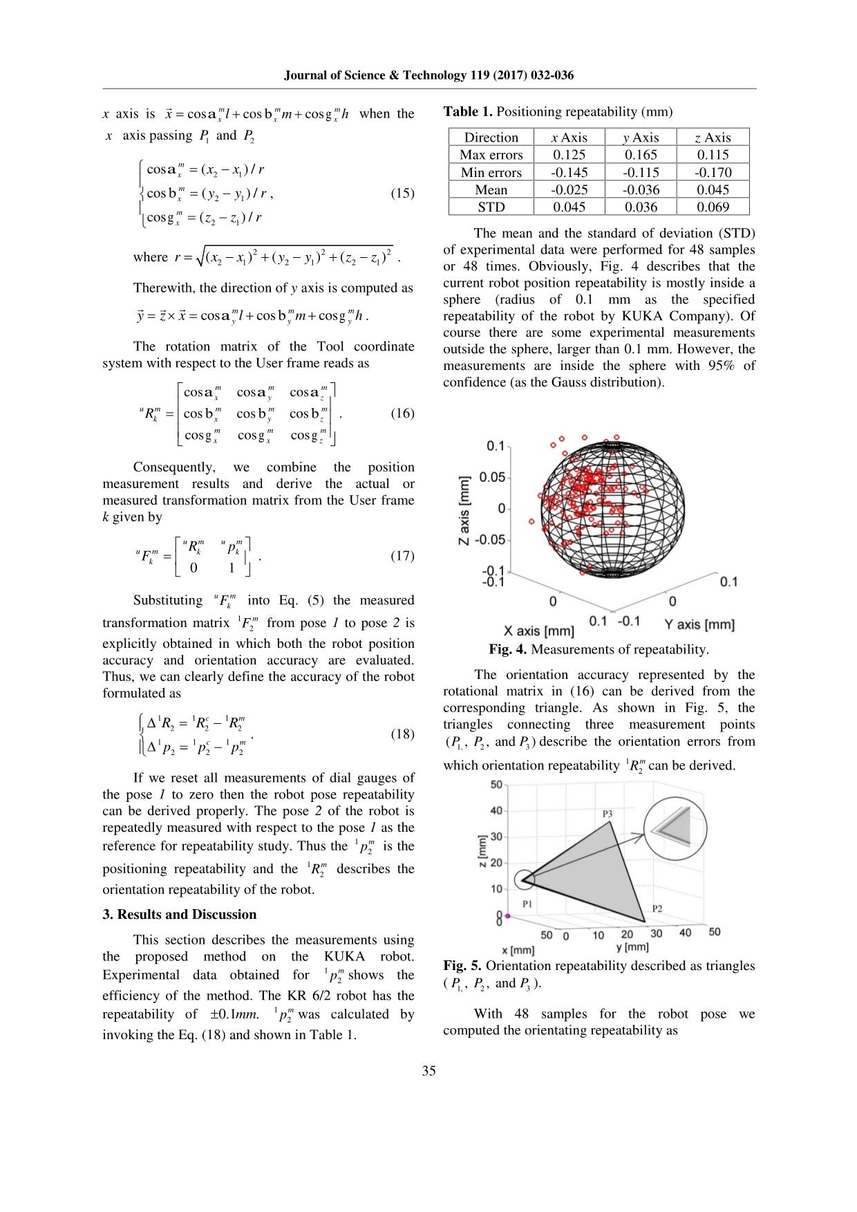
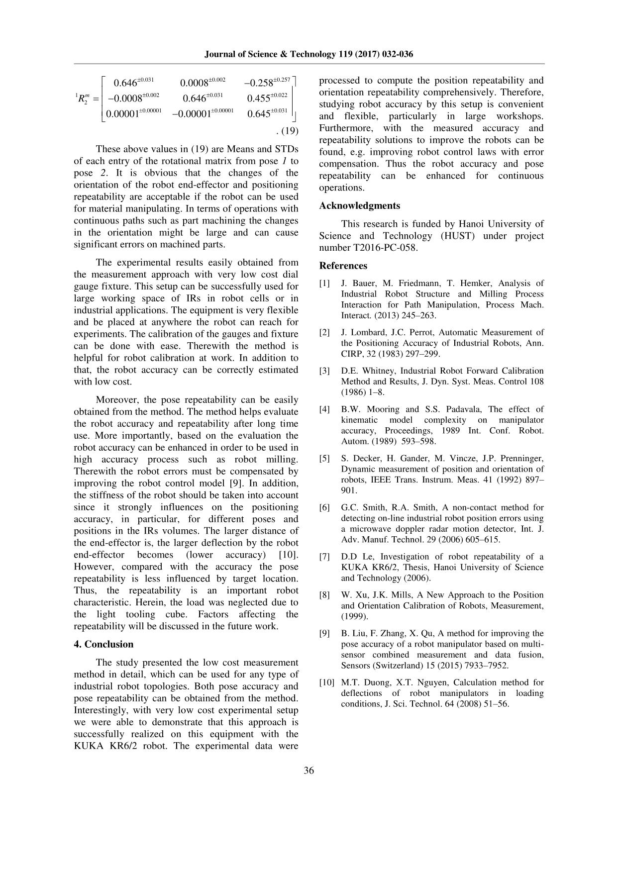
Journal of Science & Technology 119 (2017) 032-036 32 A Method for Capturing Accuracy and Pose Repeatability of Articulated Industrial Robots Duong Minh Tuan*, Le Duc Do Hanoi University of Science and Technology – No. 1, Dai Co Viet Str., Hai Ba Trung, Ha Noi, Viet Nam Received: December 21, 2016; accepted: June 9, 2017 Abstract This paper presents a low cost method for measuring accuracy and pose repeatability of industrial robots, which can be used for robot home calibration, accuracy improvements, robot control compensation or evaluating robot features. The method is proposed based on the kinematical relations of the robot joints and the geometrical data from the robot controller with respect to several defined coordinate systems. The experimental setup consists of three dial gauges, capturing position measurements of a KUKA KR6/2 robot end-effector. The positions of the end-effector are employed to estimate robot pose accuracy and repeatability. Moreover, experimental results demonstrate the efficiency of the method and can be used for improving the robot accuracy as well as robot pose repeatability in industrial applications. Keywords: Pose Repeatability, Accuracy, Industrial robot, KUKA KR 6/2 1. Introduction Recently, industrial*robots (IRs) have been more and more used to realize continuous operations such as prototyping, premachining of cast parts as well as end-machining of middle tolerance parts [1]. In addition, for repetitive tasks such as placing, welding, and assembling, the repeatability of IRs typically ranging from 0.03 to 0.1 mm and their several millimeters accuracy are commonly used. Thus, measurement approaches for accuracy and repeatability have been used for enhancing actual robot positioning accuracy. Lombard and Perrot [2] have implemented an automatic method to measure robot accuracy. The most widely applied approach is to use theodolite systems for calibration measurements [3]. Another high precision devices like Coordinate Measuring Machines (CMMs) have been widely used for industrial dimension measurement [4]. Laser Tracking Systems (LTS) [5] can combine the advantages of a large working space, high accuracy and dynamic pose measurements. However, they are high cost, and hence it is prohibitive to calibrate and measure robot poses with low costs. A simple approach to measure an error along a direction by a dial gauge has been discussed in [6]. However, this could only give accuracy for one direction. Using three dial gauge fixture for industrial robots has been investigated in [7,8]. Herein, we employ a general low cost method with a simple measurement fixture using three dial gauges to * Corresponding author: Tel: 0947 036 686 Email: tuan.duongminh@hust.edu.vn capture the robot poses for robot accuracy evaluation and calibrations. The measurement results show the efficiency of the method. 2. Method The method and the experimental setup including a KUKA KR6/2 (6kg of payload) robot at the laboratory of Machine-Tools and Tribology are presented in this section. To derive the accuracy and the repeatability from the experimental data, the coordinate systems must be defined for the proposed measurement method. All coordinate systems are depicted in Fig. 1. The world frame so-called w is fixed. The User frame can be defined at an arbitrary location in the robot cell (Fig. 2) with a designed point of a working table as the origin of the frame. The Tool frame has the origin at the Tool Center Point (TCP), see Fig.1. 2.1 Principle for Robot Pose Measurements KUKA Robot language runing on VxWork - a real time operating system (parallel with Windows), controls the robot. This can provide the position and the orientation of the end-effector (Tool frame) via 6 articulated joint angles. Thus, the robot pose can be displayed on the screen of the KUKA Control Panel (KCP). For example, when the robot moves to a specified location described by pose k for which the pose variables are defined. That means that the pose variables are determined by three position components ( , y and z )k k kx and three orientation terms, Yaw ( ),kA Pitch ( )kB and Roll ( ).kC As illustrated in Fig. 1, the robot changes pose 1 into Journal of Science & Technology 119 (2017) 032-036 33 pose 2, it needs a transformation matrix called 1 2T and these poses are expressed in the World coordinates defined by 1 wT and 2 , wT respectively. Similarly, with respect to the User frame, one can derive two transformation matrices for pose 1 and pose 2 written as 1 u F and 2 u F , respectively. The controlled transformation matrix from the World coordinate system to the Tool one describing pose k is evaluated as 1 1 2 2 3 3 4 4 5 5 6 0 1 w c w c w c w k k k k k k k k k R p T T T T T T T , (1) where w ckT is the transformation matrix from the w frame to Tool frame of pose k; 1i ikT presents the transformation matrix from joint frame i to joint frame i-1, (i=1,2,,6); and w ckR is the controlled rotational matrix from the w frame to Tool frame of pose k calculated as cos sin 0 cos 0 sin sin cos 0 0 1 0 0 0 1 sin 0 cos 1 0 0 0 cos sin 0 sin cos k k k k w c k k k k k k k k k C C B B R C C B B A A A A (2) with w ckp is the controlled position vector expressed in the w system reads as Tw ck k k kp x y z . Moreover, we obtain the relation for controlled transformation matrices of poses 1 and 2 with respect to different frames as seen in Fig. 1 1 2 1 2 w c w c cT T T 11 12 1 2c w c cT T T . (3) Consequently, the controlled transformation matrix from pose 1 to pose 2 can be determined as follows 1 1 1 2 2 2 0 1 c c c R pT , (4) where 1 2 cR and 1 2 cp are the rotation matrix and the position vector from pose 1 to pose 2 which are used to evaluate the pose measurement data, respectively. On one hand, the transformation matrix from pose 1 to pose 2 is also calculated by the KRL software using joint sensor measurements (in each robot joint). On the other hand, the matrix is specified by the commands in the robot program on the KCP. The real or measured transformation matrix from pose 1 to pose 2 can be computed as 1 2 1 2 u m u m mF F T and 11 2 1 2m u m u mT F F , (5) 1 1 1 2 2 2 0 1 m m m R pT , (6) with 1 2 mR and 1 2 mp are the rotation matrix and the position vector from pose 1 to pose 2, respectively. The robot absolute pose accuracy or the positioning and orientation accuracy are defined as a difference between the measured transformation matrix 1 2 mT and the controlled counterpart 1 2 . cT Obviously, these matrices are independent on the World and the User frames. 2.2 Experimental Setup Fig. 1. Coordinate system definition Fig. 2. Experimental setup for robot’s pose measurements of KUKA KR6/2. Fig. 2 shows the experimental setup for robot pose measurements with a fixture supporting three dial gauges with a specified space in which a tooling cube (A=50mm, made of aluminum) attached to the robot end-effector can be easily placed. The tooling Journal of Science & Technology 119 (2017) 032-036 34 P cube is fixed on the end-effector at the origin of the Tool frame and three orthonormal faces with respect to x , y and z axes are well calibrated. The three dial gauges have resolution of 0.05 mm and their stroke is of 18 mm. When the three orthonormal faces of the tooling cube touch the tips of the gauges, the slide rods of the gauges are depressed in the x , y and z directions. If the movement range of the cube is within the stroke, the dial gauges can directly indicate the change of the tooling cube position. The setup is fixed on the table and referred to the reference plate (User frame). 2.3 Positioning Accuracy The Tool Center Point can be measured. We call a reference point on the gauge fixture is P with which the TCP at pose k can be calculated by 1 1 2 2 3 3 (0.5 ) (0.5 ) , (0.5 ) k x k y k z x P A M D y P A M D z P A M D (7) where ,kx ky and kz are the coordinates of the TCP k with respect to the User frame. ,xP yP and zP are the coordinates of the point P on the gauge fixture which can be determined from measurement dimensions as shown in Fig. 3. 1 ,D 2D and 3D are the maximum travel limits of gauges 1, 2 and 3, respectively. Fig. 3. Dimensions of the experimental setup. The measurement procedure of the TCP can be addressed as follows: At first, the robot moves to a designed pose k. The tooling cube is installed on designed positions 1 ,P position. As the fixture moves so that the cube touches the tips of the dial gauges generating 1 ,P 2P and 3P points, then fixes the fixture in that place. The indications of the dial gauges are recorded. The next step is to measure and record the coordinates of point P in Fig. 3. At last, the measures xP , yP and zP are substituted into Eq. (7). Therefore, the actual position coordinates; u mkp ( , ,k k kx y z ) of the robot end-effector with respect to the User is achieved. 2.4 Orientation Accuracy To determine the orientation of the robot end- effector, the dial gauges can be placed so that they are not orthogonal together i.e. their axes do not intersect into a point. Consequently, three measuring points 1 1 1 1 ( , , )P x y z , 2 2 2 2 ( , , )P x y z and 3 3 3 3 ( , , )P x y z create a plane on which the orientation of the robot end- effector is defined. By investing this plane for each sample one can obtain the orientation of the robot tool frame. Mathematically, the plane passing the three points is constructed and the 1 1 1 1 (x , y , z )P lies in the plane yields the plane equation as 1 1 1( ) ( ) ( ) 0a x x b y y c z z , (8) where a, b and c are the direction numbers of the plane, respectively. On the other hand, the 2P and 3P lying in the plane yields 2 1 2 1 2 1 3 1 3 1 3 1 ( ) ( ) ( ) 0 ( ) ( ) ( ) 0 a x x b y y c z z a x x b y y c z z . (9) With three variables and three equations (8) and (9), the system of equations is solved to obtain the solution as 3 1 2 1 2 1 3 1 2 1 3 1 3 1 2 1 ( )( ) ( )( ) , ( )( ) ( )( ) a y y z z y y z z x x y y x x y y (10) 3 1 2 1 2 1 3 1 3 1 2 1 2 1 3 1 ( )( ) ( )( ) , ( )( ) ( )( ) b x x y y x x y y x x z z x x z z (11) 3 1 2 1 2 1 3 1 2 1 3 1 3 1 2 1 ( )( ) ( )( ) . ( )( ) ( )( ) c x x y y x x y y x x y y x x y y (12) Thereby, the normal vector of the measured plane can be evaluated by its cosines cos / ; cos / ; cos /m m mz z za q b q c q , (13) where 2 2 2q a b c . The direction vector projected on z axis is cos cos cosm m mz z zz l m h , (14) where , , andl m h are unit direction vectors of the User frame. Similarly, the direction vector of the O X P2 P3 P1 Z Y D2 M2 M3D3 M1 D1 P Journal of Science & Technology 119 (2017) 032-036 35 x axis is cos cos cosm m mx x xx l m h when the x axis passing 1P and 2P 2 1 2 1 2 1 cos ( ) / cos ( ) / cos ( ) / m x m x m x x x r y y r z z r , (15) where 2 2 22 1 2 1 2 1( ) ( ) ( )r x x y y z z . Therewith, the direction of y axis is computed as cos cos cosm m my y yy z x l m h . The rotation matrix of the Tool coordinate system with respect to the User frame reads as cos cos cos cos cos cos cos cos cos m m m x y z u m m m m k x y z m m m x x z R . (16) Consequently, we combine the position measurement results and derive the actual or measured transformation matrix from the User frame k given by 0 1 u m u m u m k k k R p F . (17) Substituting u mkF into Eq. (5) the measured transformation matrix 1 2 mF from pose 1 to pose 2 is explicitly obtained in which both the robot position accuracy and orientation accuracy are evaluated. Thus, we can clearly define the accuracy of the robot formulated as 1 1 1 2 2 2 1 1 1 2 2 2 c m c m R R R p p p . (18) If we reset all measurements of dial gauges of the pose 1 to zero then the robot pose repeatability can be derived properly. The pose 2 of the robot is repeatedly measured with respect to the pose 1 as the reference for repeatability study. Thus the 1 2 mp is the positioning repeatability and the 1 2 mR describes the orientation repeatability of the robot. 3. Results and Discussion This section describes the measurements using the proposed method on the KUKA robot. Experimental data obtained for 1 2 mp shows the efficiency of the method. The KR 6/2 robot has the repeatability of 0.1 .mm 1 2mp was calculated by invoking the Eq. (18) and shown in Table 1. Table 1. Positioning repeatability (mm) Direction x Axis y Axis z Axis Max errors 0.125 0.165 0.115 Min errors -0.145 -0.115 -0.170 Mean -0.025 -0.036 0.045 STD 0.045 0.036 0.069 The mean and the standard of deviation (STD) of experimental data were performed for 48 samples or 48 times. Obviously, Fig. 4 describes that the current robot position repeatability is mostly inside a sphere (radius of 0.1 mm as the specified repeatability of the robot by KUKA Company). Of course there are some experimental measurements outside the sphere, larger than 0.1 mm. However, the measurements are inside the sphere with 95% of confidence (as the Gauss distribution). Fig. 4. Measurements of repeatability. The orientation accuracy represented by the rotational matrix in (16) can be derived from the corresponding triangle. As shown in Fig. 5, the triangles connecting three measurement points 1, 2 3( , , and )P P P describe the orientation errors from which orientation repeatability 1 2 mR can be derived. Fig. 5. Orientation repeatability described as triangles ( 1, 2 3, , andP P P ). With 48 samples for the robot pose we computed the orientating repeatability as Journal of Science & Technology 119 (2017) 032-036 36 0.031 0.002 0.257 1 0.002 0.031 0.022 2 0.00001 0.00001 0.031 0.646 0.0008 0.258 0.0008 0.646 0.455 0.00001 0.00001 0.645 mR . (19) These above values in (19) are Means and STDs of each entry of the rotational matrix from pose 1 to pose 2. It is obvious that the changes of the orientation of the robot end-effector and positioning repeatability are acceptable if the robot can be used for material manipulating. In terms of operations with continuous paths such as part machining the changes in the orientation might be large and can cause significant errors on machined parts. The experimental results easily obtained from the measurement approach with very low cost dial gauge fixture. This setup can be successfully used for large working space of IRs in robot cells or in industrial applications. The equipment is very flexible and be placed at anywhere the robot can reach for experiments. The calibration of the gauges and fixture can be done with ease. Therewith the method is helpful for robot calibration at work. In addition to that, the robot accuracy can be correctly estimated with low cost. Moreover, the pose repeatability can be easily obtained from the method. The method helps evaluate the robot accuracy and repeatability after long time use. More importantly, based on the evaluation the robot accuracy can be enhanced in order to be used in high accuracy process such as robot milling. Therewith the robot errors must be compensated by improving the robot control model [9]. In addition, the stiffness of the robot should be taken into account since it strongly influences on the positioning accuracy, in particular, for different poses and positions in the IRs volumes. The larger distance of the end-effector is, the larger deflection by the robot end-effector becomes (lower accuracy) [10]. However, compared with the accuracy the pose repeatability is less influenced by target location. Thus, the repeatability is an important robot characteristic. Herein, the load was neglected due to the light tooling cube. Factors affecting the repeatability will be discussed in the future work. 4. Conclusion The study presented the low cost measurement method in detail, which can be used for any type of industrial robot topologies. Both pose accuracy and pose repeatability can be obtained from the method. Interestingly, with very low cost experimental setup we were able to demonstrate that this approach is successfully realized on this equipment with the KUKA KR6/2 robot. The experimental data were processed to compute the position repeatability and orientation repeatability comprehensively. Therefore, studying robot accuracy by this setup is convenient and flexible, particularly in large workshops. Furthermore, with the measured accuracy and repeatability solutions to improve the robots can be found, e.g. improving robot control laws with error compensation. Thus the robot accuracy and pose repeatability can be enhanced for continuous operations. Acknowledgments This research is funded by Hanoi University of Science and Technology (HUST) under project number T2016-PC-058. References [1] J. Bauer, M. Friedmann, T. Hemker, Analysis of Industrial Robot Structure and Milling Process Interaction for Path Manipulation, Process Mach. Interact. (2013) 245–263. [2] J. Lombard, J.C. Perrot, Automatic Measurement of the Positioning Accuracy of Industrial Robots, Ann. CIRP, 32 (1983) 297–299. [3] D.E. Whitney, Industrial Robot Forward Calibration Method and Results, J. Dyn. Syst. Meas. Control 108 (1986) 1–8. [4] B.W. Mooring and S.S. Padavala, The effect of kinematic model complexity on manipulator accuracy, Proceedings, 1989 Int. Conf. Robot. Autom. (1989) 593–598. [5] S. Decker, H. Gander, M. Vincze, J.P. Prenninger, Dynamic measurement of position and orientation of robots, IEEE Trans. Instrum. Meas. 41 (1992) 897– 901. [6] G.C. Smith, R.A. Smith, A non-contact method for detecting on-line industrial robot position errors using a microwave doppler radar motion detector, Int. J. Adv. Manuf. Technol. 29 (2006) 605–615. [7] D.D Le, Investigation of robot repeatability of a KUKA KR6/2, Thesis, Hanoi University of Science and Technology (2006). [8] W. Xu, J.K. Mills, A New Approach to the Position and Orientation Calibration of Robots, Measurement, (1999). [9] B. Liu, F. Zhang, X. Qu, A method for improving the pose accuracy of a robot manipulator based on multi- sensor combined measurement and data fusion, Sensors (Switzerland) 15 (2015) 7933–7952. [10] M.T. Duong, X.T. Nguyen, Calculation method for deflections of robot manipulators in loading conditions, J. Sci. Technol. 64 (2008) 51–56.
File đính kèm:
 a_method_for_capturing_accuracy_and_pose_repeatability_of_ar.pdf

