Nonlinear control of a tri - rotor based on the decomposition the dynamic model and feedback linearization
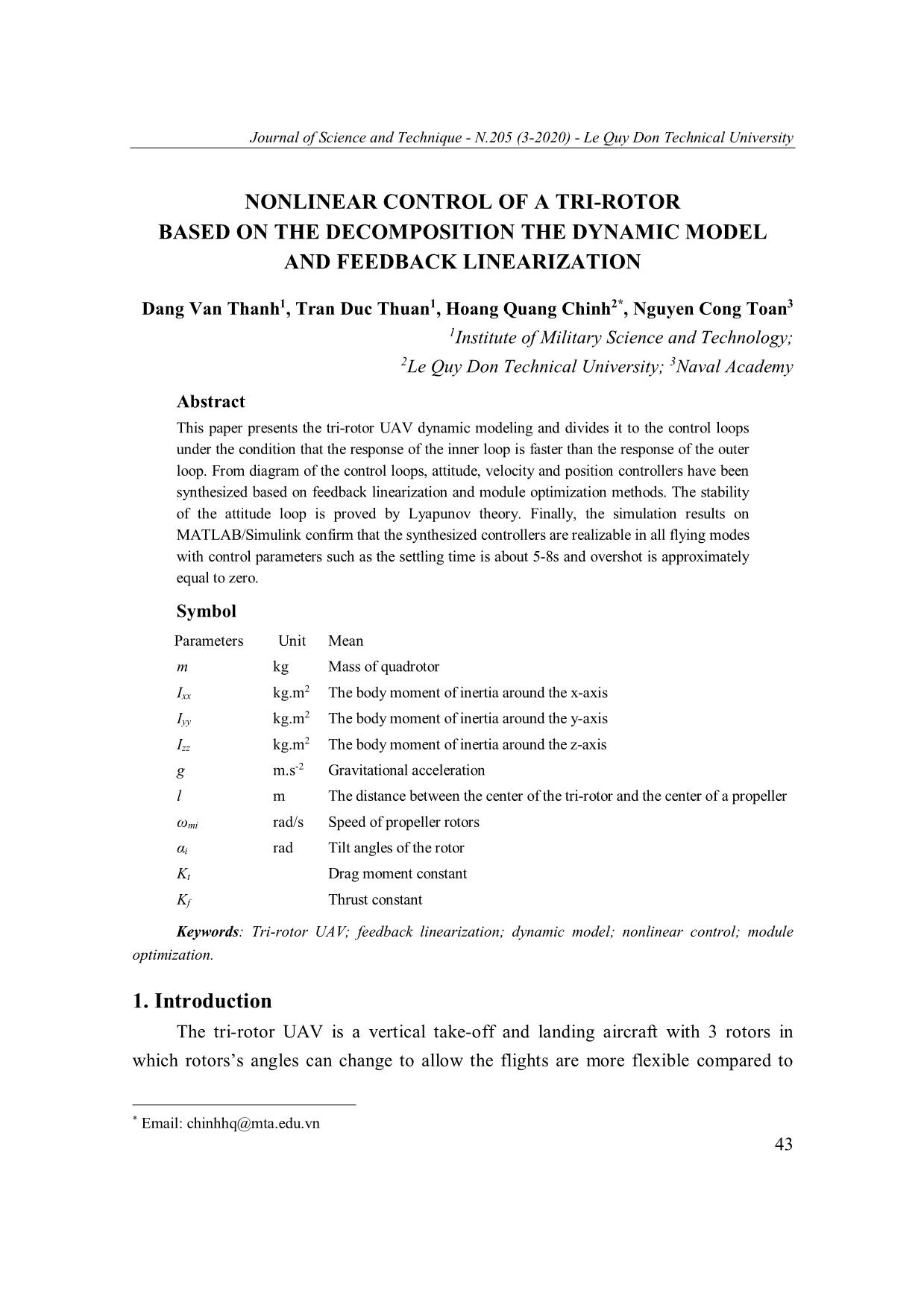
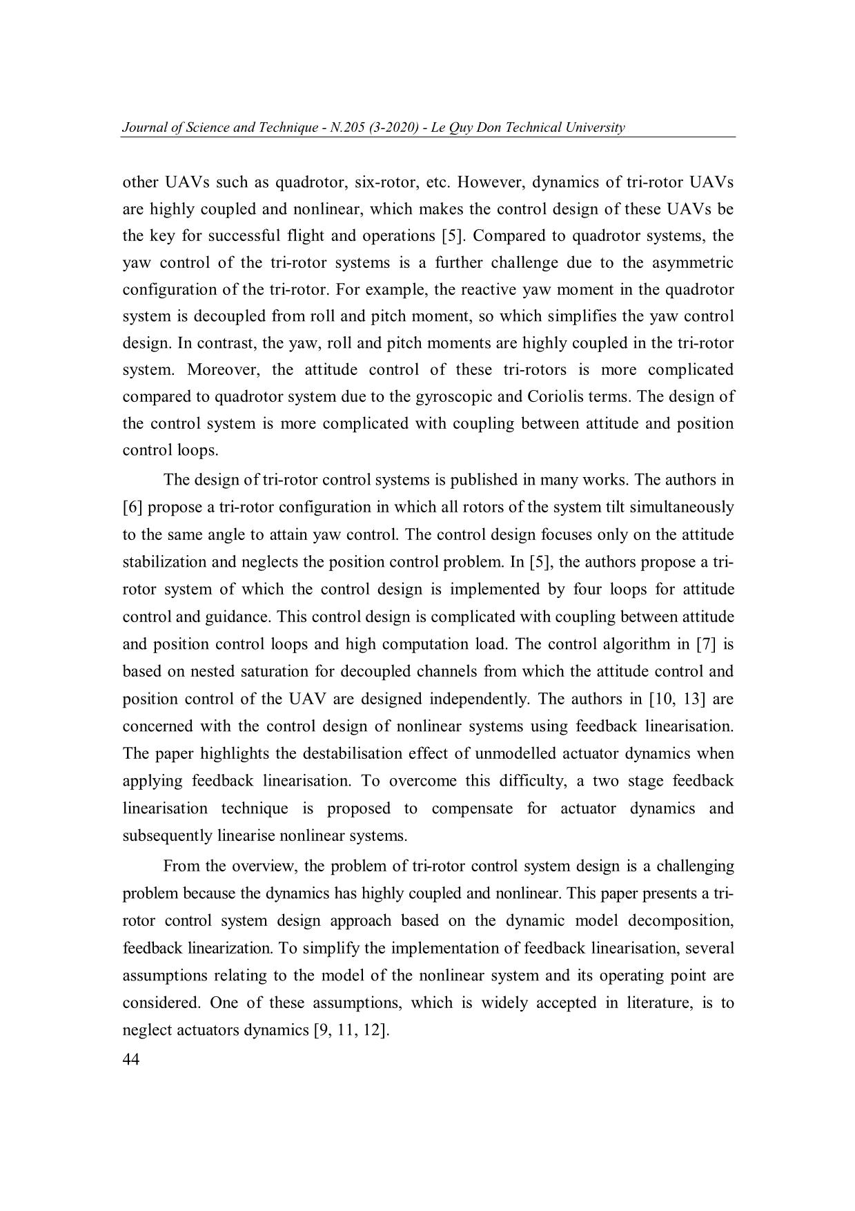
The design of tri-rotor control systems is published in many works. The authors in
[6] propose a tri-rotor configuration in which all rotors of the system tilt simultaneously
to the same angle to attain yaw control. The control design focuses only on the attitude
stabilization and neglects the position control problem. In [5], the authors propose a trirotor system of which the control design is implemented by four loops for attitude
control and guidance. This control design is complicated with coupling between attitude
and position control loops and high computation load. The control algorithm in [7] is
based on nested saturation for decoupled channels from which the attitude control and
position control of the UAV are designed independently. The authors in [10, 13] are
concerned with the control design of nonlinear systems using feedback linearisation.
The paper highlights the destabilisation effect of unmodelled actuator dynamics when
applying feedback linearisation. To overcome this difficulty, a two stage feedback
linearisation technique is proposed to compensate for actuator dynamics and
subsequently linearise nonlinear systems.
Trang 1
Trang 2
Trang 3
Trang 4
Trang 5
Trang 6
Trang 7
Trang 8
Trang 9
Trang 10
Tải về để xem bản đầy đủ
Tóm tắt nội dung tài liệu: Nonlinear control of a tri - rotor based on the decomposition the dynamic model and feedback linearization
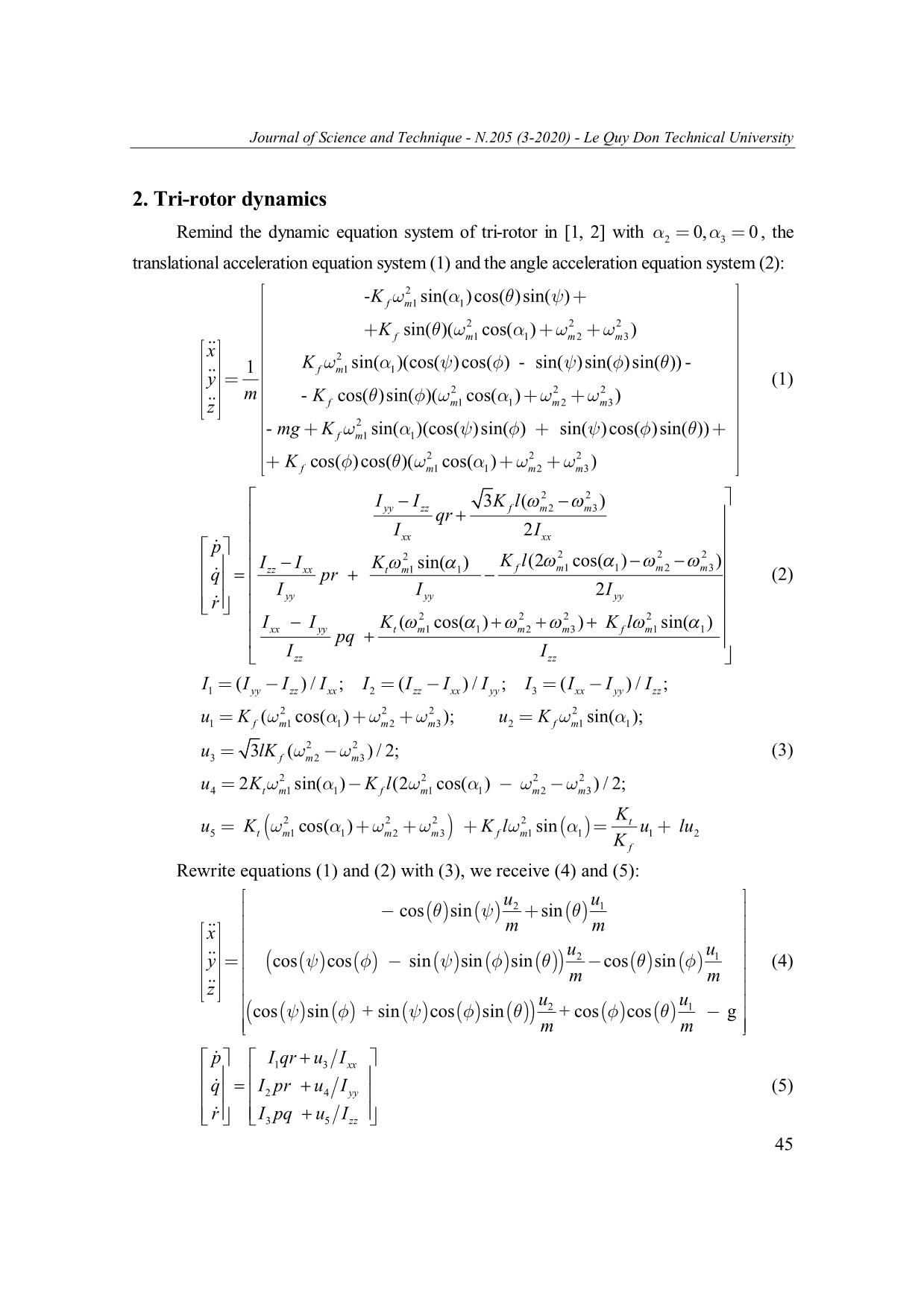
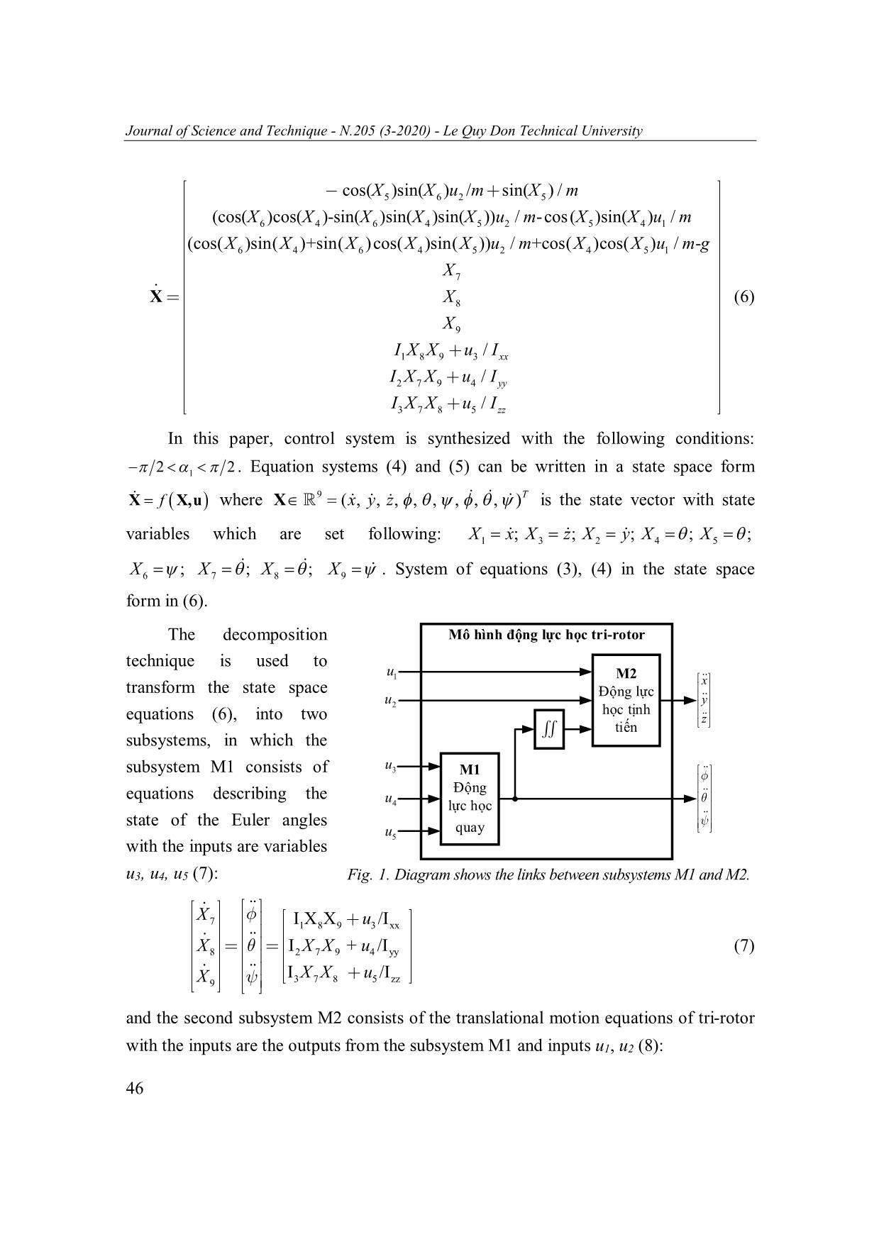
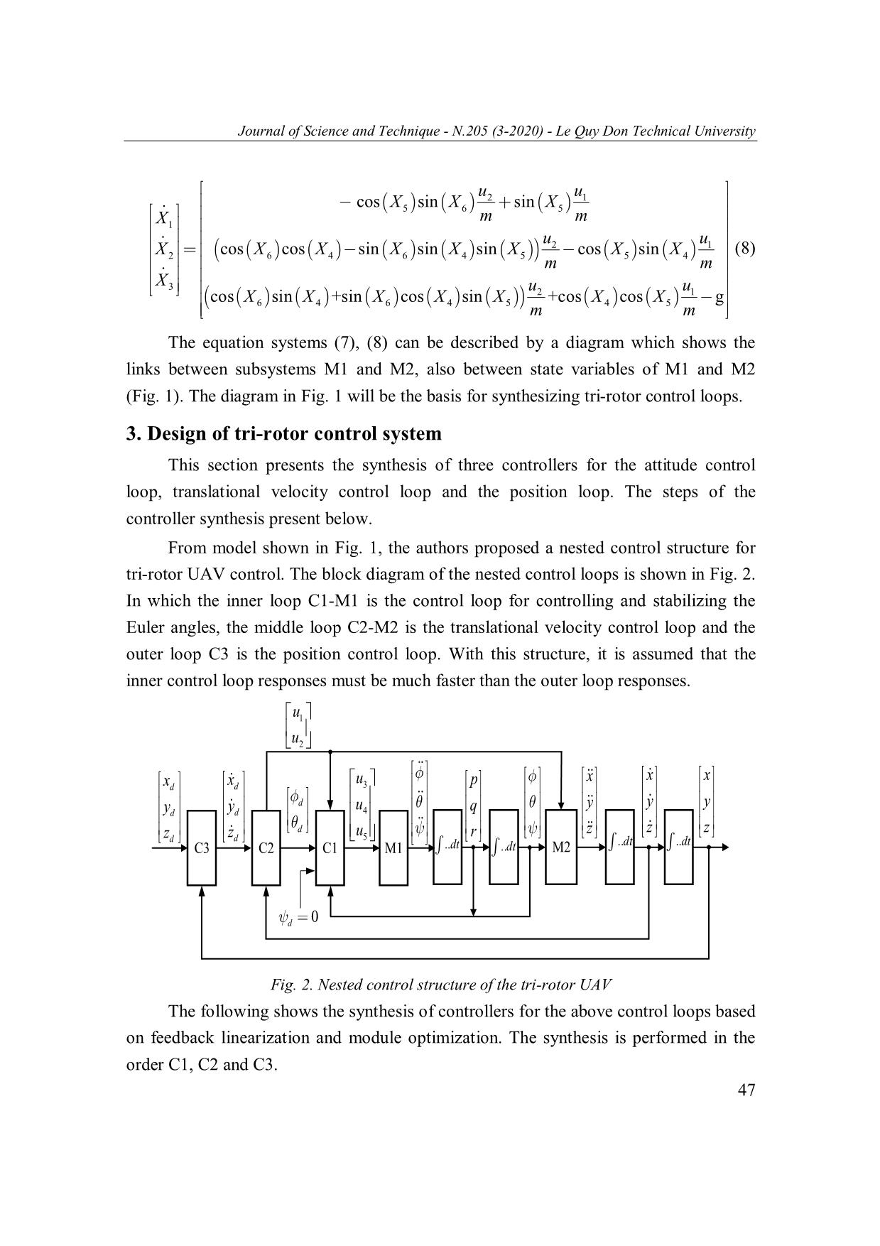
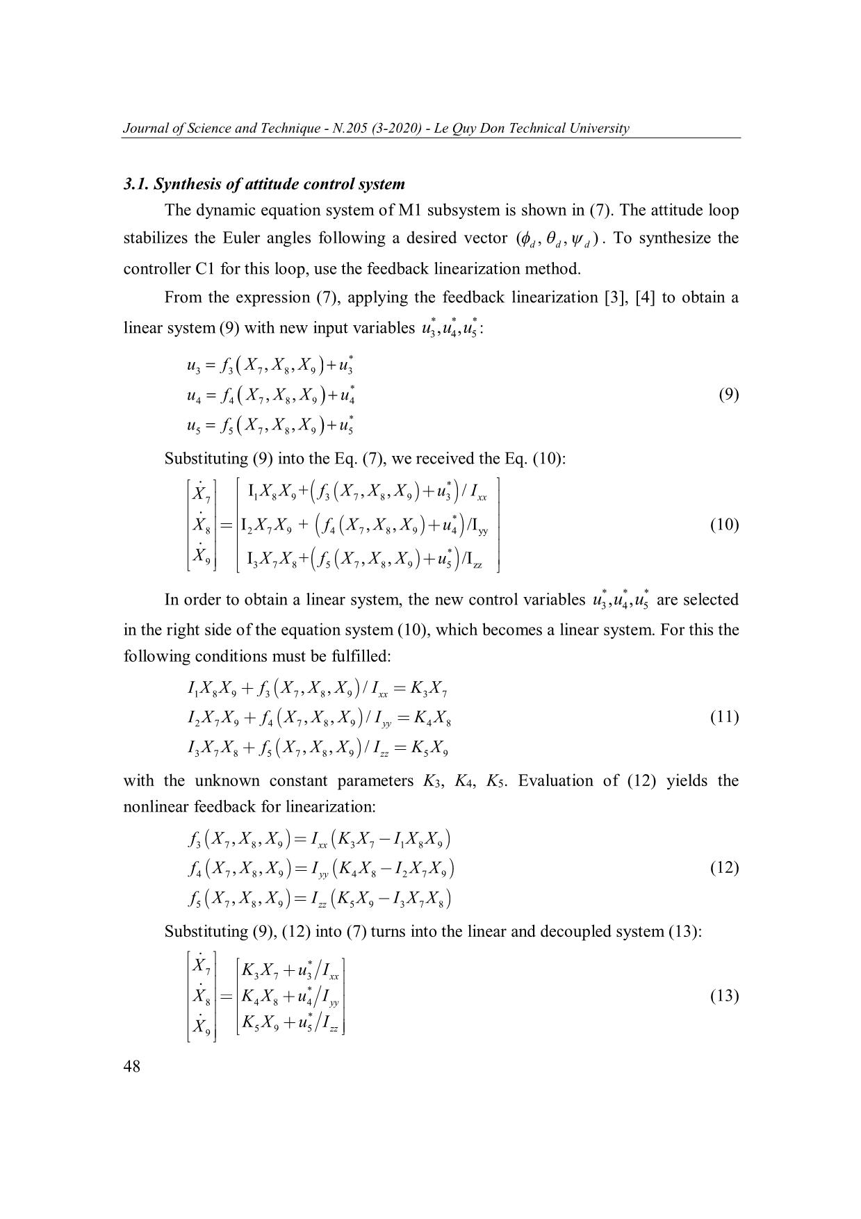
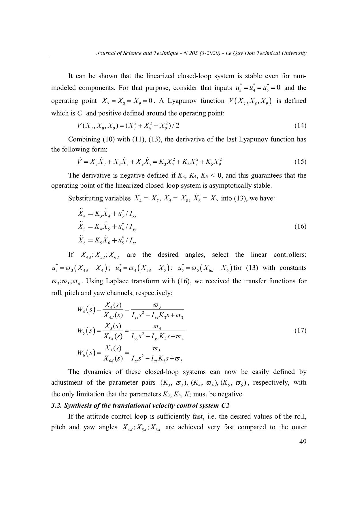
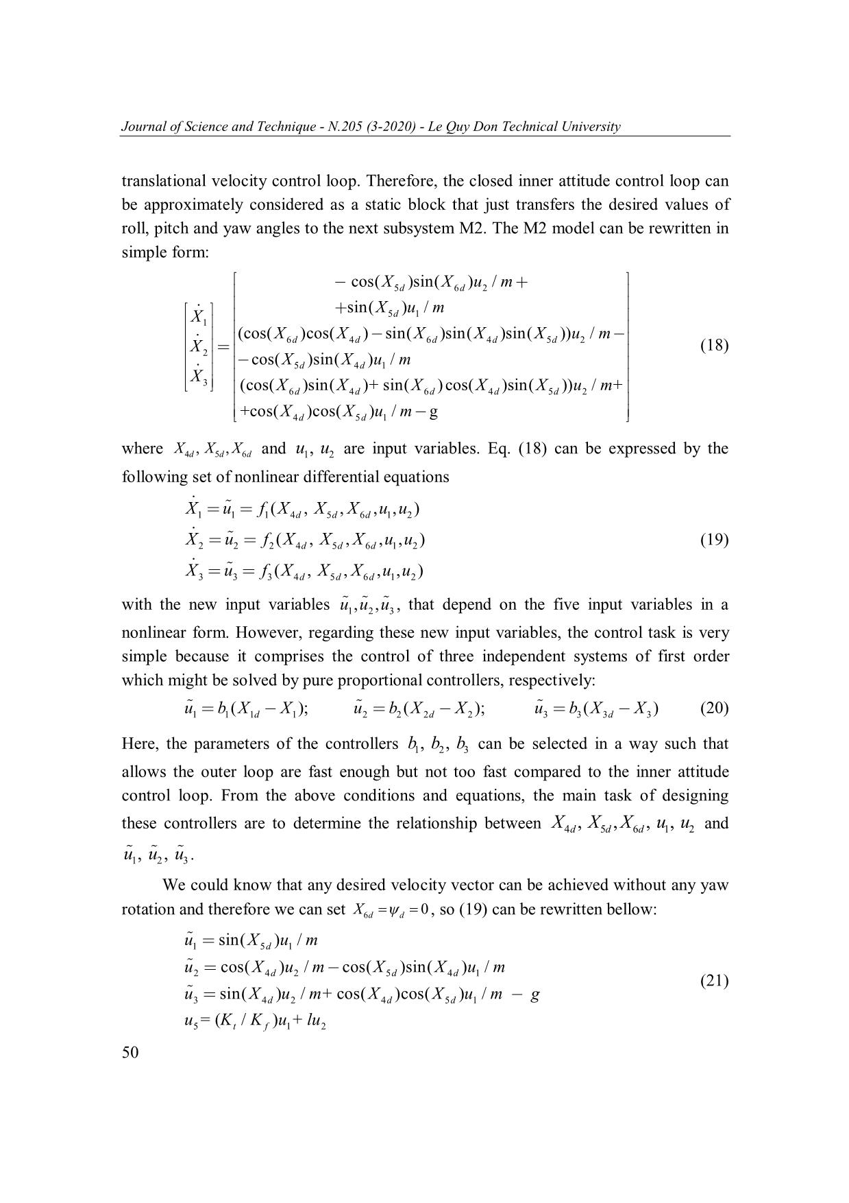
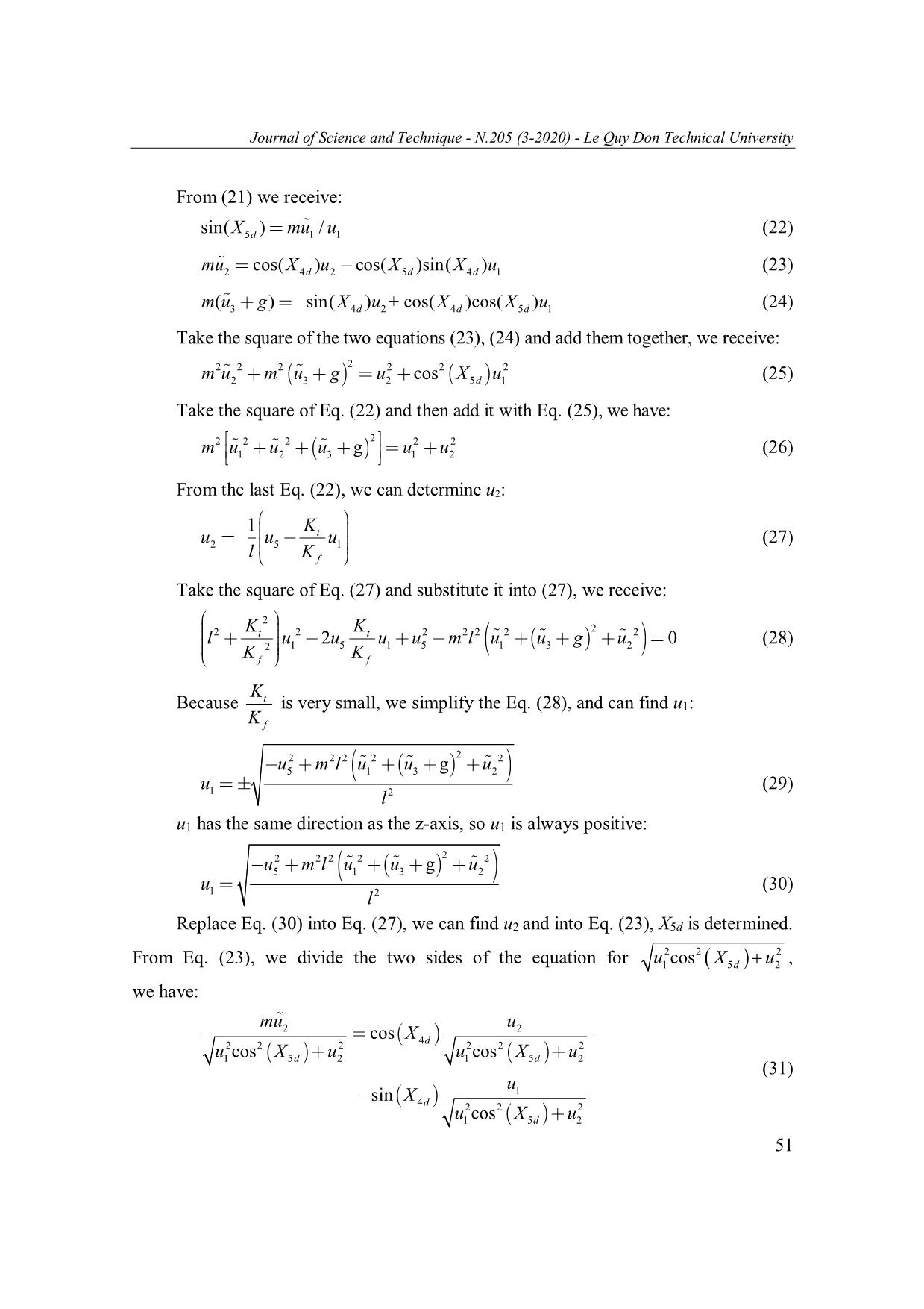
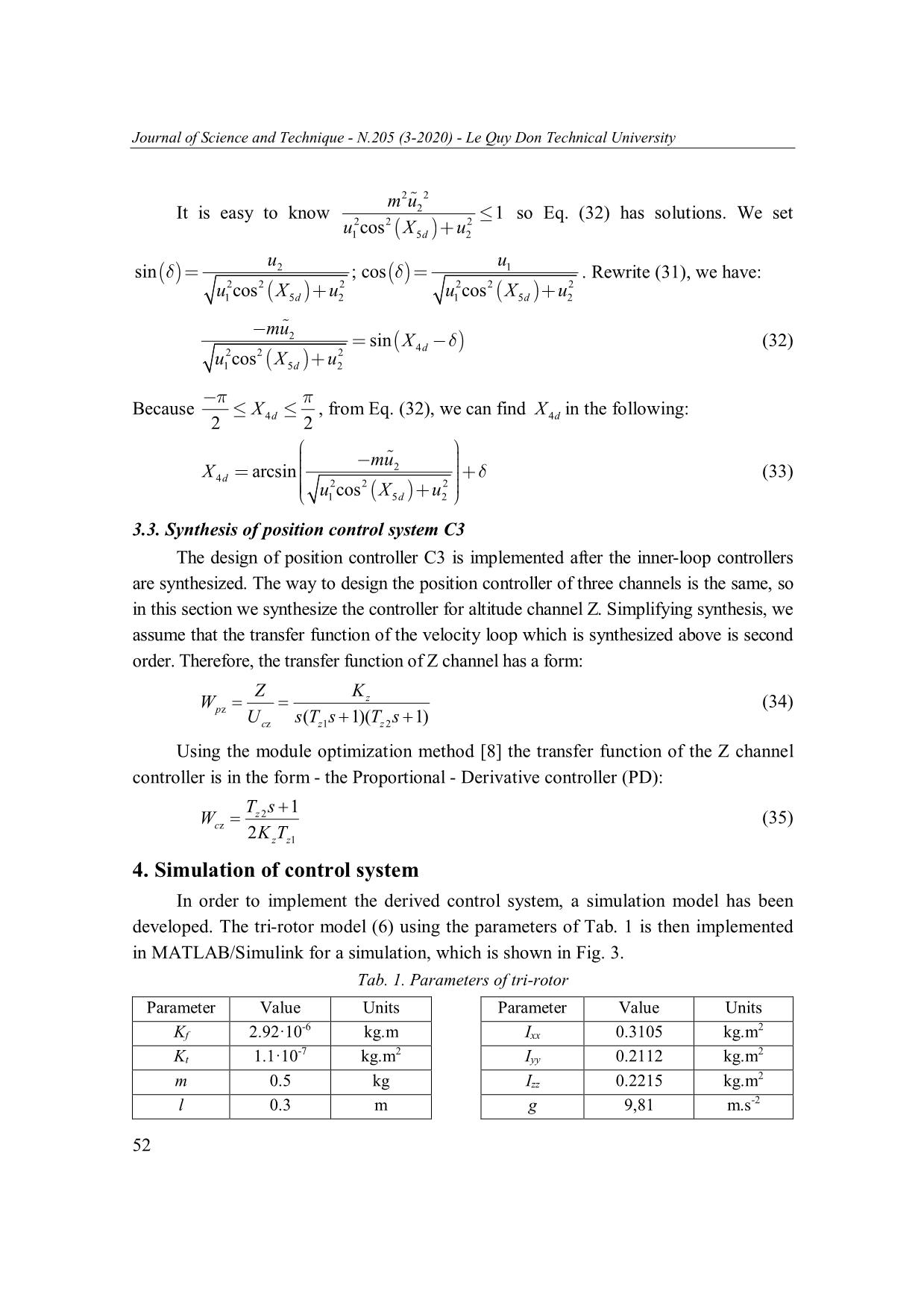
Journal of Science and Technique - N.205 (3-2020) - Le Quy Don Technical University NONLINEAR CONTROL OF A TRI-ROTOR BASED ON THE DECOMPOSITION THE DYNAMIC MODEL AND FEEDBACK LINEARIZATION Dang Van Thanh1, Tran Duc Thuan1, Hoang Quang Chinh2*, Nguyen Cong Toan3 1Institute of Military Science and Technology; 2Le Quy Don Technical University; 3Naval Academy Abstract This paper presents the tri-rotor UAV dynamic modeling and divides it to the control loops under the condition that the response of the inner loop is faster than the response of the outer loop. From diagram of the control loops, attitude, velocity and position controllers have been synthesized based on feedback linearization and module optimization methods. The stability of the attitude loop is proved by Lyapunov theory. Finally, the simulation results on MATLAB/Simulink confirm that the synthesized controllers are realizable in all flying modes with control parameters such as the settling time is about 5-8s and overshot is approximately equal to zero. Symbol Parameters Unit Mean m kg Mass of quadrotor 2 Ixx kg.m The body moment of inertia around the x-axis 2 Iyy kg.m The body moment of inertia around the y-axis 2 Izz kg.m The body moment of inertia around the z-axis g m.s-2 Gravitational acceleration l m The distance between the center of the tri-rotor and the center of a propeller ωmi rad/s Speed of propeller rotors αi rad Tilt angles of the rotor Kt Drag moment constant Kf Thrust constant Keywords: Tri-rotor UAV; feedback linearization; dynamic model; nonlinear control; module optimization. 1. Introduction The tri-rotor UAV is a vertical take-off and landing aircraft with 3 rotors in which rotors’s angles can change to allow the flights are more flexible compared to * Email: chinhhq@mta.edu.vn 43 Journal of Science and Technique - N.205 (3-2020) - Le Quy Don Technical University other UAVs such as quadrotor, six-rotor, etc. However, dynamics of tri-rotor UAVs are highly coupled and nonlinear, which makes the control design of these UAVs be the key for successful flight and operations [5]. Compared to quadrotor systems, the yaw control of the tri-rotor systems is a further challenge due to the asymmetric configuration of the tri-rotor. For example, the reactive yaw moment in the quadrotor system is decoupled from roll and pitch moment, so which simplifies the yaw control design. In contrast, the yaw, roll and pitch moments are highly coupled in the tri-rotor system. Moreover, the attitude control of these tri-rotors is more complicated compared to quadrotor system due to the gyroscopic and Coriolis terms. The design of the control system is more complicated with coupling between attitude and position control loops. The design of tri-rotor control systems is published in many works. The authors in [6] propose a tri-rotor configuration in which all rotors of the system tilt simultaneously to the same angle to attain yaw control. The control design focuses only on the attitude stabilization and neglects the position control problem. In [5], the authors propose a tri- rotor system of which the control design is implemented by four loops for attitude control and guidance. This control design is complicated with coupling between attitude and position control loops and high computation load. The control algorithm in [7] is based on nested saturation for decoupled channels from which the attitude control and position control of the UAV are designed independently. The authors in [10, 13] are concerned with the control design of nonlinear systems using feedback linearisation. The paper highlights the destabilisation effect of unmodelled actuator dynamics when applying feedback linearisation. To overcome this difficulty, a two stage feedback linearisation technique is proposed to compensate for actuator dynamics and subsequently linearise nonlinear systems. From the overview, the problem of tri-rotor control system design is a challenging problem because the dynamics has highly coupled and nonlinear. This paper presents a tri- rotor control system design approach based on the dynamic model decomposition, feedback linearization. To simplify the implementation of feedback linearisation, several assumptions relating to the model of the nonlinear system and its operating point are considered. One of these assumptions, which is widely accepted in literature, is to neglect actuators dynamics [9, 11, 12]. 44 Journal of Science and Technique - N.205 (3-2020) - Le Quy Don Technical University 2. Tri-rotor dynamics Remind the dynamic equation system of tri-rotor in [1, 2] with 2 0, 3 0 , the translational acceleration equation system (1) and the angle acceleration equation system (2): -K 2 sin( ) cos( )sin( ) f m1 1 2 2 2 K fsin( )( m1cos ( 1 ) m 2 m 3 ) x ... n and module optimization. The synthesis is performed in the order C1, C2 and C3. 47 Journal of Science and Technique - N.205 (3-2020) - Le Quy Don Technical University 3.1. Synthesis of attitude control system The dynamic equation system of M1 subsystem is shown in (7). The attitude loop stabilizes the Euler angles following a desired vector (,,)d d d . To synthesize the controller C1 for this loop, use the feedback linearization method. From the expression (7), applying the feedback linearization [3], [4] to obtain a *** linear system (9) with new input variables u3,, u 4 u 5 : * u3 f 3 X 7,, X 8 X 9 u 3 * u4 f 4 X 7,, X 8 X 9 u 4 (9) * u5 f 5 X 7,, X 8 X 9 u 5 Substituting (9) into the Eq. (7), we received the Eq. (10): IXXI +f X , X , X u* / X 7 18 9 3 7 8 9 3 xx * XXX8 I2 7 9 + f 4 X 7 , X 8 , X 9 u 4 / I yy (10) * X 9 IXX +f X , X ,X u / I 37 8 5 7 8 9 5 zz *** In order to obtain a linear system, the new control variables u3,, u 4 u 5 are selected in the right side of the equation system (10), which becomes a linear system. For this the following conditions must be fulfilled: I1XXXXX8 9 f 3 7,,/ 8 9 Ixx K 3 X 7 I2XXXXX7 9 f 4 7,,/ 8 9 Iyy K 4 X 8 (11) I3 X 7X 8 f5 XXX7,,/ 8 9 IXzz K 5 9 with the unknown constant parameters K3, K4, K5. Evaluation of (12) yields the nonlinear feedback for linearization: f3 XXXXX7,, 8 9 Ixx K 3 X 7 I 1 8 9 f4 XXXXX7,, 8 9 Iyy K 4 X8 I 2 7 9 (12) f5 XX7,, 8 X 9 Izz K 5X 9 I 3 XX7 8 Substituting (9), (12) into (7) turns into the linear and decoupled system (13): * X 7 KX u I 3 7 3 xx X KX u* I (13) 8 4 8 4 yy * X KX5 9 u5 I zz 9 48 Journal of Science and Technique - N.205 (3-2020) - Le Quy Don Technical University It can be shown that the linearized closed-loop system is stable even for non- *** modeled components. For that purpose, consider that inputs u3 u 4 u 5 0 and the operating point XXX7 8 9 0 . A Lyapunov function VXXX 7,, 8 9 is defined which is C1 and positive defined around the operating point: 2 2 2 VXXXXXX(7 , 8 , 9 ) ( 7 8 9 ) / 2 (14) Combining (10) with (11), (13), the derivative of the last Lyapunov function has the following form: 2 2 2 VXXXXXXKXKXKX 77 88 99 37 48 59 (15) The derivative is negative defined if K3, K4, K5 < 0, and this guarantees that the operating point of the linearized closed-loop system is asymptotically stable. Substituting variables XXXXXX4 7 , 5 8 , 6 9 into (13), we have: * XKX4 3 4 u3 / I xx * XKX5 4 5 u4 / I yy (16) * X 6 KX5 6 u5 / I zz If XXX;; are the desired angles, select the linear controllers: 4d 5 d 6 d * * * u3 3 X 4d X 4 ; u4 4 X 5d X 5 ; u5 5 X 6d X 6 for (13) with constants 3;; 5 6 . Using Laplace transform with (16), we received the transfer functions for roll, pitch and yaw channels, respectively: X4 () s 3 W4 s 2 X4d() s I xx s I xx K 3 s 3 X5 () s 4 W5 s 2 (17) X5d() s I yy s I yy K 4 s 4 X6() s 5 W6 s 2 X6d() s I zz s I zz K 5 s 5 The dynamics of these closed-loop systems can now be easily defined by adjustment of the parameter pairs (),KKK3, 3 , ( 4 , 4 ) ( 5 , 5 ) , respectively, with the only limitation that the parameters K3, K4, K5 must be negative. 3.2. Synthesis of the translational velocity control system C2 If the attitude control loop is sufficiently fast, i.e. the desired values of the roll, pitch and yaw angles XXX4d;; 5 d 6 d are achieved very fast compared to the outer 49 Journal of Science and Technique - N.205 (3-2020) - Le Quy Don Technical University translational velocity control loop. Therefore, the closed inner attitude control loop can be approximately considered as a static block that just transfers the desired values of roll, pitch and yaw angles to the next subsystem M2. The M2 model can be rewritten in simple form: cos(XX )sin( )u / m 5d 6 d 2 sin(X )u / m 5d 1 X1 (cos(XXXXX )cos( ) sin( )sin( )sin( ))u / m 6d 4 d 6 d 4 d 5 d 2 (18) X 2 cos(XX5d )sin( 4 d )u1 / m X 3 (cos(XXXXX )sin( )+ sin( )cos( )sin( ))u / m + 6d 4 d 6 d 4 d 5 d 2 +cos(XX4d )cos(5 d )u1 / m g where XXX4d, 5 d , 6 d and u1, u 2 are input variables. Eq. (18) can be expressed by the following set of nonlinear differential equations X1 u 1 f 1(,) X 4d, X 5 d , X 6 d ,u1 u 2 X2 u2 f 2(,) X 4d, X 5 d,, X 6 d u1u 2 (19) X3 u3 f 3(,) X 4d, X 5 d , X 6 d ,u1 u2 with the new input variables u1,, u 2 u 3 , that depend on the five input variables in a nonlinear form. However, regarding these new input variables, the control task is very simple because it comprises the control of three independent systems of first order which might be solved by pure proportional controllers, respectively: ubXX1111 (d ); ubXX 2222 ( d ); ubXX 3333 ( d ) (20) Here, the parameters of the controllers b1, b 2 , b 3 can be selected in a way such that allows the outer loop are fast enough but not too fast compared to the inner attitude control loop. From the above conditions and equations, the main task of designing these controllers are to determine the relationship between X4d, X 5 d , X 6 d , u 1 , u 2 and u1, u 2 , u 3 . We could know that any desired velocity vector can be achieved without any yaw rotation and therefore we can set X6d d 0 , so (19) can be rewritten bellow: u1 sin( X 5d )u1 / m u cos( X )u / m cos( X )sin( X ) u / m 2 4d2 5 d 4 d 1 (21) u3 sin( X 4d )u2 / m + cos( X4 d )cos( X 5 d ) u 1 / m g u5 = (Kt / Kf ) u1 + l u2 50 Journal of Science and Technique - N.205 (3-2020) - Le Quy Don Technical University From (21) we receive: sin(X5d ) m u 1 / u1 (22) mu2 cos( X 4d )u2 cos(X 5 d )sin(X 4 d )u1 (23) m( u3 g ) sin( X4d )u2 + cos( X 4 d )cos( X 5 d )u 1 (24) Take the square of the two equations (23), (24) and add them together, we receive: 22 2 2 2 2 2 mu2 m u 3 g u 2 cos X 5d u 1 (25) Take the square of Eq. (22) and then add it with Eq. (25), we have: 2 m2 u2 u 2 u g u 2 u 2 (26) 12 3 1 2 From the last Eq. (22), we can determine u2: 1 K u u t u (27) 2 5 1 l K f Take the square of Eq. (27) and substitute it into (27), we receive: 2 KK 2 l2 t u 2 2 u t u u2 m 2 l 2 u 2 u g u 2 0 (28) 2 1 51 5 1 3 2 KKf f Kt Because is very small, we simplify the Eq. (28), and can find u1: K f 2 2 2 2 2 2 u5 m l u1 u 3 g u 2 u (29) 1 l 2 u1 has the same direction as the z-axis, so u1 is always positive: 2 2 2 2 2 2 u5 m l u1 u 3 g u 2 u (30) 1 l 2 Replace Eq. (30) into Eq. (27), we can find u2 and into Eq. (23), X5d is determined. 2 2 2 From Eq. (23), we divide the two sides of the equation for u1cos X 5d u 2 , we have: mu u 2 cos X 2 2 2 24d 2 2 2 u1cos XX5d u 2 u 1 cos 5 d u 2 (31) u sin X 1 4d 2 2 2 u1 cos X 5d u2 51 Journal of Science and Technique - N.205 (3-2020) - Le Quy Don Technical University 2 2 m u2 It is easy to know 2 2 2 1 so Eq. (32) has solutions. We set u1cos X 5d u 2 u u sin 2 ; cos 1 . Rewrite (31), we have: 2 2 2 2 2 2 u1cos X 5d u 2 u 1 cos X 5 d u2 mu 2 sin X (32) 2 2 2 4d u1 cos X 5d u2 Because X , from Eq. (32), we can find X in the following: 24d 2 4d mu2 X arcsin (33) 4d 2 2 2 u1cos X 5d u 2 3.3. Synthesis of position control system C3 The design of position controller C3 is implemented after the inner-loop controllers are synthesized. The way to design the position controller of three channels is the same, so in this section we synthesize the controller for altitude channel Z. Simplifying synthesis, we assume that the transfer function of the velocity loop which is synthesized above is second order. Therefore, the transfer function of Z channel has a form: Z K z Wpz (34) Ucz s( T z 1 s 1)( T z 2 s 1) Using the module optimization method [8] the transfer function of the Z channel controller is in the form - the Proportional - Derivative controller (PD): Tz 2 s 1 Wcz (35) 2KTz z1 4. Simulation of control system In order to implement the derived control system, a simulation model has been developed. The tri-rotor model (6) using the parameters of Tab. 1 is then implemented in MATLAB/Simulink for a simulation, which is shown in Fig. 3. Tab. 1. Parameters of tri-rotor Parameter Value Units Parameter Value Units -6 2 Kf 2.92·10 kg.m Ixx 0.3105 kg.m -7 2 2 Kt 1.1·10 kg.m Iyy 0.2112 kg.m 2 m 0.5 kg Izz 0.2215 kg.m l 0.3 m g 9,81 m.s-2 52 Journal of Science and Technique - N.205 (3-2020) - Le Quy Don Technical University Fig. 3. Diagram simulating the tri-rotor control system a) Position responses b) Angular responses c) Translational velocity responses d) Angular velocity responses Fig. 4. The simulation results of the tri-rotor control system with synthesized controllers The parameters of the velocity controllers are chosen as b1 1; b2 1; b3 1 while the design parameters of the inner loop attitude controllers are KKK3 4 5 80 and 3 4 40 , 5 30; the coefficients of position controllers PD are KPX 0.25; KPY 0.25; KPZ 0.25; KKKDX DY DZ 0.1. In simulation, we will implement with some steps: At the first time, the tri-rotor vertical takes off to height Zd = 30, after 53 Journal of Science and Technique - N.205 (3-2020) - Le Quy Don Technical University 20 seconds, UAV moves following the Y direction with Yd = 10; after the next 10 seconds, flies to the X direction with Xd = 20. At the time equal 40s, tri-rotor reduces the altitude from 30m to 25m and flies to the Y direction more 5mm, simultaneously. At the time point 60s, tri-rotor implements from 25m to 30m in Z direction. At the time point 70, tri-rotor moves back 5m in the X direction. At the time point 90, tri-rotor lands at the start point. The obtained control result is shown in Fig. 4. In general, the controller shows good performance with tracking in all channels for take off, hovering and landing state. The controller succeeds to maintain the stability of the vehicle and follow the reference trajectory. The settling time of the system is about 5-8s with overshot is approximately zero. Both translational and rotational velocities converge to zero when tri-rotor at hovering state. At the time when X, Y channels change which also cause changing a little in Z channel. This is reflected from dynamic model. 5. Conclusion In this paper, non-linear control systems for tri-rotor UAV is designed based on the dynamic model decomposition into a nested structure with the constraint that the responses of inner loops is much faster than the responses of outer loops. The controllers of the attitude loop, the translational loop and the position loop are synthesized using feedback linearization, modulus optimum. Stability of attitude loop is proved by Lyapunov theory. The simulation model has built on Matlab/Simulink from the tri-rotor dynamics and the synthesized controllers. The simulation results have shown the good performance of control system in take off, hover and landing modes with control parameters such as the settling time is about 5-8s and overshot is approximately equal zero. References 1. Trần Đức Thuận, Đặng Văn Thành (2017). Khảo sát chuyển động UAV tri-rotor trong trường hợp một động cơ thay đổi tốc độ và góc nghiêng. Tạp chí Nghiên cứu KH&CNQS, 52. 2. Hoàng Quang Chính, Nguyễn Công Toàn (2013). Nghiên cứu xây dựng mô hình toán và mô phỏng UAV tri-rotor. Tuyển tập công trình Hội nghị toàn quốc lần thứ 2 về Điều khiển và Tự động hóa - VCCA 2013. 3. Nguyễn Doãn Phước (2012). Phân tích và điều khiển hệ phi tuyến, Nxb Bách khoa. 4. Nguyễn Doãn Phước (2009). Lý thuyết điều khiển nâng cao, Nxb Khoa học và Kỹ thuật. 5. Y. L. a. J. J. Z. R. Huang (November-December 2009). Guidance, navigation, and control system design for tripropeller vertical-takeoff-and-landing unmanned air vehicle. Journal of Aircraft, 46(6), pp. 1837-1856. 54 Journal of Science and Technique - N.205 (3-2020) - Le Quy Don Technical University 6. A. S. O. G. a. R. L. J. Escareno (2008). Triple tilting rotor mini-UAV: Modeling and embedded control of the attitude. in American Control Conference. 7. R. L. a. J. E. S. Salazar-Cruz (2009). Stabilization and nonlinear control for a novel tri-rotor mini-aircraf. Control Engineering Practice, 17(8), pp. 886-894. 8. Đào Hoa Việt (2011). Bài tập ví dụ và Thực hành điều khiển tự động truyền động điện, Học viện KTQS, Hà Nội. 9. Cai, B. M. Chen, K. Peng, M. Dong, and T. H. Lee (2008). Modeling and control of the yaw channel of a UAV helicopter. IEEE Transactions on Industrial Electronics, 55(9), pp. 3426-3434. 10. Mohamed K. M. and A. Lanzon (2013). Effect of Unmodelled Actuator Dynamics on Feedback Linearised Systems and a Two Stage Feedback Linearisation Method. Conference, IEEE 52nd Annual Conference on Decision and Control (CDC). 11. J. Chen and Y. Wang (December 2010). The guidance and control of small net-recovery UAV. In Proceedings of the 2011 Seventh International Conference on Computational Intelligence and Security (CIS), Hainan, China, pp. 1566-1570. 12. Y. Kang and J. K. Hedrick (2009). Linear tracking for a fixed-wing UAV using nonlinear model predictive control. IEEE Transactions on Control Systems Technology, 17(5), pp. 1202-1210. 13. Hoang Van Huy, Hoang Quang Chinh, Dao Hoa Viet (2017). Synthesis of the Quadrotor Control Loop Using Feedback Linearization and Optimum Modulus Methods. Tạp chí Khoa học và Kỹ thuật, 186(10-2017), Học viện KTQS, tr. 87-99. ĐIỀU KHIỂN PHI TUYẾN TRI-ROTOR DỰA TRÊN PHÂN CHIA MÔ HÌNH ĐỘNG LỰC HỌC VÀ TUYẾN TÍNH HÓA PHẢN HỒI Tóm tắt: Bài báo trình bày việc xây dựng mô hình động lực học UAV tri-rotor và phân chia mô hình động lực học thành cấu trúc các vòng điều khiển lệ thuộc với điều kiện ràng buộc rằng đáp ứng của các vòng trong nhanh hơn đáp ứng của những vòng ngoài. Từ sơ đồ các vòng điều khiển, các bộ điều khiển tư thế, vận tốc và vị trí đã được tổng hợp bằng phương pháp tuyến tính hóa phản hồi và tối ưu hóa mô đun. Tính ổn định của vòng điều khiển tư thế đã được chứng minh bằng lý thuyết Lyapunov. Cuối cùng, các kết quả mô phỏng trên MATLAB/Simulink khẳng định rằng các bộ điều khiển đã tổng hợp làm việc được trong tất cả các chế độ bay với các thông số điều khiển như thời gian quá độ từ 5-8s và độ quá điều chỉnh xấp xỉ bằng không. Từ khóa: Tri-rotor UAV; tuyến tính hóa phản hồi; mô hình động lực học; điều khiển phi tuyến; tối ưu hóa mô đun. Received: 02/4/2019; Revised: 04/4/2020; Accepted for publication: 06/4/2020 55
File đính kèm:
 nonlinear_control_of_a_tri_rotor_based_on_the_decomposition.pdf

