Hydrodynamic and dynamic analysis to determine the longitudinal hydrodynamic coefficients of an autonomous underwater vehicle
During the underwater vehicle scheme design
period, the simulation and evaluation of the stability
of submarine is an important task. Simulation of the
motion of an underwater vehicle requires the
numerical solution of six-coupled non-linear
differential equations. Three of these equations
describe the translational motions of the vehicle, the
remaining three equations describe rotational
motions of the vehicle about some fixed point on the
body [1]. This fixed point is usually taken
to be either the centre of mass (CM) or the centre of
buoyancy (CB) of the vehicle. Detailed derivations
and discussions of these equations of motion can be
found in many references [2], [3]. Traditionally, the
methods to predict the hydrodynamic derivatives of
underwater vehicles could be classified into three
types: the semi-empirical method, the potential flow
method, and the captive-model experiments including
the oblique towing tests, the rotating arm experiments
and the Planar Motion Mechanism (PMM) [1].
With the semi-empirical method, the
complicated underwater vehicle shape usually could
not be taken into full account. The potential theory
could predict the inertial hydrodynamic coefficients
satisfactorily, but with the viscous terms neglected
[3]. The PMM experiment may be the most effective
way, but it requires special facilities and equipment
and it is both time-consuming and costly [3], as not
economical at the preliminary design stage.
*Corresponding author: Tel.: (+84) 913.223.160
Email: quang.le@hust.edu.vn
This paper shows the results by using the semiexperimental method (used U.S Air Force DATCOM
method). This method is based on the techniques
developed in the aeronautical industry. The calculated
values were then compared with CFD results and
other data available [2].
Trang 1
Trang 2
Trang 3
Trang 4
Trang 5
Trang 6
Tóm tắt nội dung tài liệu: Hydrodynamic and dynamic analysis to determine the longitudinal hydrodynamic coefficients of an autonomous underwater vehicle
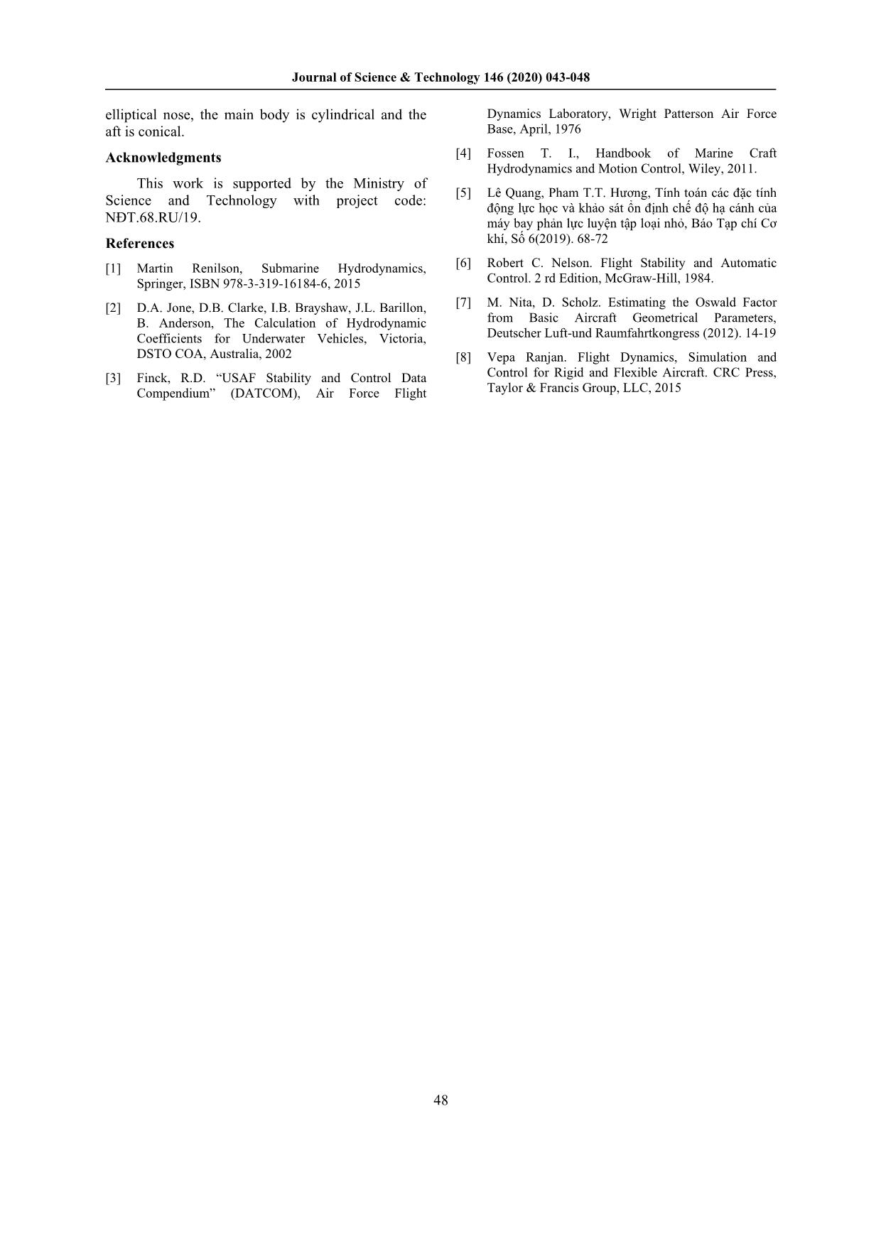
Journal of Science & Technology 146 (2020) 043-048 Hydrodynamic and Dynamic Analysis to Determine the Longitudinal Hydrodynamic Coefficients of an Autonomous Underwater Vehicle Le Quang*, Phan Anh Tuan, Pham Thi Thanh Huong Hanoi University of Science and Technology, No. 1, Dai Co Viet, Hai Ba Trung, Hanoi, Viet Nam Received: June 07, 2020; Accepted: November 12, 2020 Abstract A useful tool for understanding the performance of an Autonomous Underwater Vehicle (AUV) is a dynamic simulation of the motions of the vehicle. To perform the simulation, the hydrodynamic coefficients of the vehicle must be first provided. These coefficients are specific to the vehicle and provide the description of hydrodynamic forces and moments acting on the vehicle in an underwater environment. This paper provides a method for the calculation and evaluation of the hydrodynamic coefficients of an AUV. The presence methodology is therefore one useful tool for determining an underwater vehicle’s dynamic stability. The calculated values have been compared with experimental results of a torpedo shape. It was concluded that the methods could calculate accurate values of the hydrodynamic coefficients for a specific AUV shape with its elliptical nose Keywords: Stability, Autonomous Underwater Vehicles (AUV), simulation, hydrodynamic coefficients 1. Introduction* This paper shows the results by using the semi- During the underwater vehicle scheme design experimental method (used U.S Air Force DATCOM period, the simulation and evaluation of the stability method). This method is based on the techniques of submarine is an important task. Simulation of the developed in the aeronautical industry. The calculated motion of an underwater vehicle requires the values were then compared with CFD results and numerical solution of six-coupled non-linear other data available [2]. differential equations. Three of these equations 2. Equation of AUV Motion describe the translational motions of the vehicle, the remaining three equations describe rotational The equations of motion for a submarine are motions of the vehicle about some fixed point on the similar to those for an aircraft, they include all six body [1]. This fixed point is usually taken degrees of freedom [1],[5],[7]. For a submarine, it is to be either the centre of mass (CM) or the centre of normal to take the origin as the longitudinal centre of buoyancy (CB) of the vehicle. Detailed derivations gravity (LCG), rather than midships, as this simplifies and discussions of these equations of motion can be the equations, and for a submarine, this position is found in many references [2], [3]. Traditionally, the fixed (unlike for a surface ship). The axis system used methods to predict the hydrodynamic derivatives of is shown in the notation in Table 1. underwater vehicles could be classified into three types: the semi-empirical method, the potential flow Table 1. Notation method, and the captive-model experiments including Position Velocity Force/Moment the oblique towing tests, the rotating arm experiments and the Planar Motion Mechanism (PMM) [1]. Surge x u X With the semi-empirical method, the Sway y v Y complicated underwater vehicle shape usually could Heave z w Z not be taken into full account. The potential theory could predict the inertial hydrodynamic coefficients Roll φ p K satisfactorily, but with the viscous terms neglected [3]. The PMM experiment may be the most effective Pitch θ q M way, but it requires special facilities and equipment Yaw ψ r N and it is both time-consuming and costly [3], as not economical at the preliminary design stage. Appendage δ Propulsion n *Corresponding author: Tel.: (+84) 913.223.160 Email: quang.le@hust.edu.vn 43 Journal of Science & Technology 146 (2020) 043-048 The equations of motion are based on Newton’s subscript refers to conditions in the assumed Second Law: Force = Mass × Acceleration. In this reference state. The partial derivatives are known as case, the force, the left-hand side of the equation, is hydrodynamic coefficients, hydrodynamic the hydrodynamic force acting on the submarine, and derivatives, or stability derivatives, and are evaluated the right-hand side is the rigid body dynamics, the at the reference condition. right-hand side of the equation is given as follows: There are 36 hydrodynamic coefficients which • •• 22 could be evaluated to describe the dynamics of the X=−+−++−++ m u v r wq x( q r) y pq r z p r q G GG( ) ( ) vehicle. If the vehicle has certain symmetries •• •however then many of these coefficients are zero. For 22 Y= m v − wp + ur + x qp +− r y( r+ p) + z qr − p example, if the x-z plane is a plane of symmetry so GG G ( ) ( ) that the vehicle has Left/Right symmetry, then terms • •• 22 such as Yu, Yw, Lu, Lw, etc. will all be zero. Yu, for Z= mwuqvpx − ++ rpqy −+ rqp + − z( p+ q) G( ) GG( ) example, is the contribution to the component of •• •force in the y-direction due to motion in the x- 22 K= I p +−( I I) qr - r + pq I +( r− q) I +− pr q I direction. For a body with Left/Right symmetry, it is xx xx yy ( ) zx yz ( ) xy easy to see that this contribution will always be zero. •• +m y w-uq +− vp z v-wp + ur GG( ) ( ) •• • 22 MI= q+−( I I) rp-p + qrI +( p− r) I +− qprI y y xx zz ( ) xy zx ( ) yx •• −m x w- u q +− v p z u- vr + wq GG( ) ( ) •• • 22 N= I r +( I − I) pq-qrpI + +( q− p) I+− rqpI zz yy xx ( ) yx xy ( ) zx •• +m x v- wp +− ur y w-uq + vp GG( ) ( ) (1) X, Y, Z, K, M, and N are the total hydrodynamic surge, sway, and heave forces, and roll, pitch, and Fig. 1 Coordinate system used fo AUV yaw moments respectively. If these hydrodynamic Some authors [2],[4] had concluded that the forces and moments can be determined as functions non-zero coefficients for axe-symmetric AUVs are of time for a maneuvering submarine, then the Xu, Xv, Xw, Zw, Zq, Mw and Mq in the movement of AUV can be simulated. In addition, if longitudinal plane, and Yv, Yr, Nv, and Nr in the the effects of geometry on these forces and moments lateral plane. are understood then this can be used to assist in the design of the submarine. The expressions for the In [6] discussing aerodynamic derivatives for forces and moments then take the form: aeroplanes, notes that for symmetric aircraft the derivatives of the asymmetric or lateral forces and X=+++ X XuXvXwXpXqXr + + + 0 uvw p pr moments, Y, L, and N, with respect to the symmetric or longitudinal motion variables u, w, and q, will be Y=+++ Y YuYvYwYpYqYr + + + 0 uvw p pr zero. This implies that Yu, Yw, Yq, Lu, Lw, Lq, Nu, Nw, and Nq are zero for aircraft, and bodies which Z=+++ Z ZuZvZwZpZqZr + + + 0 uvw p pr exhibit similar symmetry properties. All the derivatives of the symmetric forces (X, Z) and L=+++ L LuLvLwLpLqLr + + + 0 uvw p pr moments (M) with respect to the asymmetric variables (v, p and r) can be neglected. This implies M=+++ M MuMvMwMpMqMr + + + 0 uvw p pr that Xv, Xp, Xr, Zv, Zp, Zr, Mv, Mp and Mr are zero. N=+++ N NuNvNwNpNqNr + + + This result also could be applied to an AUV 0 uvw p pr For the longitudinal coefficients, Xu, Zw, Zq, (2) Mw and Mq are important while Zu and Mu are less In equations the subscript notation represents important. The other longitudinal coefficients such as ∂ X Yv, Yr, Nv, and Nr are neglected because of the partial differentiation, so that X = u and the zero u ∂t symmetry in geometry of the AUV. 44 Journal of Science & Technology 146 (2020) 043-048 3. Determination of hydrodynamic coefficients S ' = − b ZCq,B L (7) In the present work, the hydrodynamic stability l2 q,β derivatives are determined through DATCOM method [3], combined with CFD simulation. Peterson 3.4 Calculation of M' : The pitching uses the DATCOM method for the calculation of the q,B '' ' moment/pitch rate curve slope [2]: hydrodynamic coefficients ZMwB,,;; wB ZqB, and ' ' ' 2 M qB, for the bare hull, and ZwB, and M wB, for the x lx mV cm bare hull plus horizontal tail configuration. This is 1−− − l Sl l l presented below. The prime notation above indicates CC= tb (8) mm α x V a dimensionless coefficient, and Peterson accepted q,B ,B 1−−m l Sl the convention that all derivatives are non- tb dimensional with respect to the body cross-sectional area Sb and the body length l S MC' = − b (9) ' q,B 2 m Calculation of ZwB, : Peterson’s expression [2] l q,β for Zw for the body alone is: where lc is the distance from the nose to the entre of S buoyancy and Stb is the cross sectional area of the ' =−+b Z CC (3) truncated base. The tail-alone lift-curve slope is w,B 2 LD l α,B 0 calculated using the following [2]: where C is the body alone lift-curve slope and Lα,B 2π AR S C = t (10) C is the drag coefficient at zero lift. Given by CFD L 2 2 S D0 α ,T 2++ 4( AR) 1 + tan λ b ( c /2) simulation. ' where AR is the aspect ratio of the tail, λc/2 is the Calculation of M w,B : The pitching moment/ sweep angle at the half-chord line, and St is the total angle of attack is calculated in DATCOM by tail planform area. The expression for the combined applying a viscous correction to the Munk moment body/tail lift-curve slope is then [2] 2π AR = CL 2 kk− l α ,wing 22 22 ( ) v dS 2++ 4 4πλ( AR) ( 1 + tanc/2) /C α C = 21∫ (x− x) dx (4) L m S l dx m αβ, 0 b (11) where xm is defined as being the distance from the For C is actually an approximate expression Lα ,T nose to the moment reference center and lv is the axial location of separation. The final expression for the which has been derived using thin wing theory, pitching moment is then: CLα= 2πα. The interference of the fuselage with the wing [8], as well as the contribution of the fuselage S itself to the lift, is taken into account using the MC' =b (5) w,B 2 m following expression: l α,β C= KC (12) L wf L ' αα,w f , wing Calculation of Zq,B : Peterson considers only the contribution of the bare hull to Zq and Mq [2]. where Kwf is a correction factor which has the form: x 2 m dd CC=1 − (6) ff LLl K =+−1 0.025 0.25 (13) q,Bα ,B wf bb where xm is the distance from the nose to the moment where d is the maximum fuselage diameter and b is reference center. Zq is then given by f the wing span [6], [7]. 45 Journal of Science & Technology 146 (2020) 043-048 C Lα AR = ∞ = (14) C α L C Lα AR = ∞ 1+ π AR C2 CC= + L (15) DD 0 π AR where AR is the aspect ratio, C is the wing lift L Fig. 3. Velocity contour around AUV coefficient 5. Results and Discussions 4. The AUV Model First, the drag and lift coefficients of AUV To identify hydrodynamic coefficients of the motion have been calculated by using CFD method. AUV, a model of AUV is used in this study. The The steady state CFD was successfully applied to principal parameters of AUV are shown in Table 2. simulate the straight line. Reynolds-averaged Navier- Table 2. Principal technical parameters of AUV Stokes (RANS) equations are time-averaged equations of motion for fluid flow and as an approach Symbol Content Value to solve Navier-Stokes equations [5]. Fig. 3 shows the (Unit) velocity contour around AUV and for calculation of Length L(mm) 3013 the necessary values as CL, CD, CM when using the Height H(mm) 462 tools above. Diameter D(mm), df 300 The AUV has been carried simulation with its Draught without water T(mm) velocity from 0.5 m/s to 5.0 m/s and the vehicle 296 in the 4 floats moves in infinite fluid with three different turbulent models of k − ε . Fig.3 shows the velocity contour Weight M(Kg) 200 around AUV for 3m/s. Table 3 and Fig.5 show the Wingspan b(mm) 462 drag and drag coefficient of the AUV whit diferent Sea water density ρ(kg/m3) 1035 velocities. The drag coefficient of AUV is identified Velocity V(m/s) 2.0 by using equation (16) below. 2 Moments of inertia Ixx(kgm ) 2.2184 2 F C = D (16) Centre of gravity G(x,y,z) 0, 0, 0 D ρ SV2 Centre of buoyancy B(xb,yb,zb) 0, 0, 50 3 FD(N) - Force resistance (drag); ρ = 1035kg/m - density of sea water, S = 0.07065m2 - reference area (the cross perpendicular section with motion). Fig. 2. Geometry of underwater vehicle Fig. 4. Velocity contour around the aft of AUV 46 Journal of Science & Technology 146 (2020) 043-048 Table 3. Drag/Drag coefficient in the function of The hydrodynamic stability derivatives are velocity determined through DATCOM method, combined with CFD simulation. For the longitudinal Velocity (m/s) Drag FD (N) Drag coefficient coefficients note that Xu, Zw, Zq, Mw, and Mq were CD important coefficients, while Zu and Mu were less 0.5 2.22 0.24 significant. These other longitudinal coefficients are 1.0 8.77 0.24 zero [8]. Table 5 shows the calculated values for the 1.5 18.92 0.23 four longitudinal hydrodynamic coefficients for this 2.0 36.41 0.24 AUV. 2.5 53.92 0.23 3.0 82.14 0.25 Table 5. Longitudinal hydrodynamic coefficients 3.5 115.99 0.26 Coefficients Value Math 4.0 151.50 0.25 calculated (x10-3) formula 4.5 191.75 0.24 Z’W -1.79 (3) 5.0 236.73 0.25 M’W 0.882 (5) Z’q -14.4 (7) M’q -0.455 (9) The data experimental for this AUV is not available so in order to check the correctness of this method, we use the test values obtained from documentation [2]. Table 6 shows the comparison of calculated and experimental values for Torpedo 13 done by Hyguess [2]. Table 6. Comparison of calculated and experimental values. Fig. 5. Resistance of AUV Coefficient Value Experiment Percentage Fig. 4 shows the velocity around the aft body of calculated difference AUV when the AUV moves near the seabed and for Z’W -0.593 -0.60 1.2 calculation of tail lift curve slope. M’W 0.993 0.99 0.0 Using the math formulas from equations (10) to Z’q -0.209 -0.20 5.0 (15), the parameters of aft Hydroplanes are calculated in Table 4. M’q -0.074 -0.08 7.5 Method CFD for the calculation of the lift and Table 6 shows that the percentage difference drag coefficient of alone wing are clearly presented in between values calculated and experimental is (6) and do not need to be repeated here. acceptable. From there the results calculated in table 5 can be accepted. Table 4. Designed and calculated parameters of Aft Hydroplanes NACA 0012 6. Conclusion Parameter Values Remark A detailed description of the calculation of each of four longitudinal hydrodynamic coefficients of Aspect ratio of the tail 3.7 AR AUV is identified by DATCOM method, based on Sweep angle at the half- 20o λc/2 techniques developed in the aeronautical industry. In chord line this paper, DATCOM method is used to calculate the Total 0.0579m2 St hydrodynamic coefficients for an AUV with a tail planform area torpedo shape. -1 Tail-alone lift-curve slope 5.63 rad CLα The calculated values have been compared with -1 Tail-alone lift-curve slope 3.49 rad CLα,t experimental results of a torpedo shape. It was -1 Tail-fuselage lift-curve 3.79 rad CLα,tf concluded that the methods described above could slope calculate accurate values of the hydrodynamic coefficients for a specific AUV shape with its Drag coefficient of tail 0.0213 CDt 47 Journal of Science & Technology 146 (2020) 043-048 elliptical nose, the main body is cylindrical and the Dynamics Laboratory, Wright Patterson Air Force aft is conical. Base, April, 1976 Acknowledgments [4] Fossen T. I., Handbook of Marine Craft Hydrodynamics and Motion Control, Wiley, 2011. This work is supported by the Ministry of [5] Lê Quang, Pham T.T. Hương, Tính toán các đặc tính Science and Technology with project code: động lực học và khảo sát ổn định chế độ hạ cánh của NĐT.68.RU/19. máy bay phản lực luyện tập loại nhỏ, Báo Tạp chí Cơ References khí, Số 6(2019). 68-72 [1] Martin Renilson, Submarine Hydrodynamics, [6] Robert C. Nelson. Flight Stability and Automatic Springer, ISBN 978-3-319-16184-6, 2015 Control. 2 rd Edition, McGraw-Hill, 1984. [2] D.A. Jone, D.B. Clarke, I.B. Brayshaw, J.L. Barillon, [7] M. Nita, D. Scholz. Estimating the Oswald Factor B. Anderson, The Calculation of Hydrodynamic from Basic Aircraft Geometrical Parameters, Coefficients for Underwater Vehicles, Victoria, Deutscher Luft-und Raumfahrtkongress (2012). 14-19 DSTO COA, Australia, 2002 [8] Vepa Ranjan. Flight Dynamics, Simulation and [3] Finck, R.D. “USAF Stability and Control Data Control for Rigid and Flexible Aircraft. CRC Press, Compendium” (DATCOM), Air Force Flight Taylor & Francis Group, LLC, 2015 48
File đính kèm:
 hydrodynamic_and_dynamic_analysis_to_determine_the_longitudi.pdf

