Evaluation of the effect of the concentration of seeding particles on spike - excitation doppler uvp measurement
Abstract. In the study of fluid flows, one of the important parameters is the spatialtemporal velocity distribution. Experimental measurement of the parameter is required
for the development and validation of various models in this field. Techniques for the
measurement of flow velocity at single points have been in operation with great success
for many years. However, there are situations where the measured data at one point is
obviously not enough to understand structures in, e.g., turbulent/transient flows. One
of the well-established and powerful methods for measuring velocity distribution is the
UVP - Ultrasonic Velocity Profile method that enables measurements of the instantaneous
velocity profile along a measurement line, i.e. the sound path. The new application of
spike excitation along with the Doppler signal processing to the UVP method has recently
been successfully tested. Regarding this new method, factors influencing the measurement result require further careful investigations. This study addresses, to some extent,
the effect of the seeding-particle concentration on the results of spike-excitation UVP measurements. For the investigation, experimental measurements of water pipe flow have
been carefully executed for a wide range of the particle concentration. The dependence of
the measured data on the particle concentration is evaluated and reported. The result of
this study suggests an appropriate range of the seeding-particle concentration in setting
up spike-excitation UVP measurements.
Keywords: flow velocity measurement, velocity profile, UVP - Ultrasonic Velocity Profile,
spike excitation, doppler signal processing.
Trang 1
Trang 2
Trang 3
Trang 4
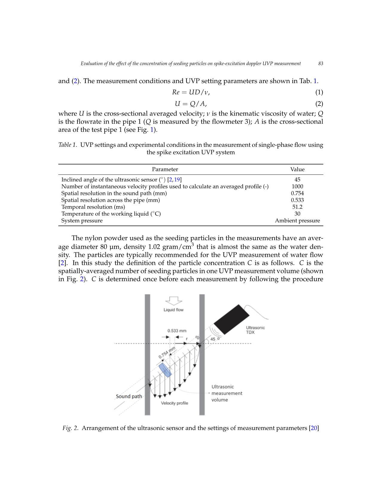
Trang 5
Trang 6
Trang 7
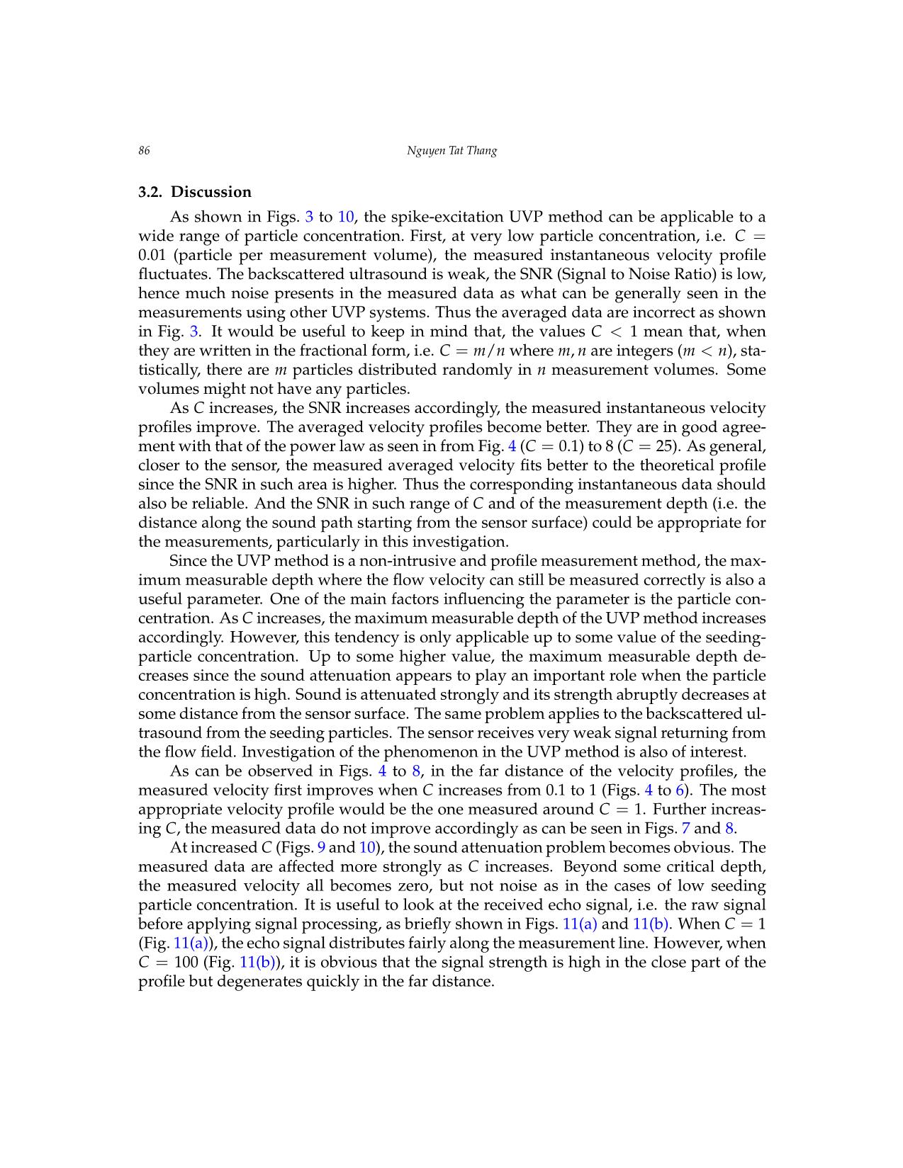
Trang 8
Trang 9
Trang 10
Tải về để xem bản đầy đủ
Tóm tắt nội dung tài liệu: Evaluation of the effect of the concentration of seeding particles on spike - excitation doppler uvp measurement
 Vietnam Journal of Mechanics, VAST, Vol.43, No. 1 (2020), pp. 79 – 90
 DOI: https://doi.org/10.15625/0866-7136/15554
 EVALUATION OF THE EFFECT OF THE CONCENTRATION
 OF SEEDING PARTICLES ON SPIKE-EXCITATION DOPPLER
 UVP MEASUREMENT
 Nguyen Tat Thang1,∗
 1Posts and Telecommunications Institute of Technology, Hanoi, Vietnam
 ∗E-mail: thangnt@ptit.edu.vn
 Received: 20 September 2020 / Published online: 21 December 2020
 Abstract. In the study of fluid flows, one of the important parameters is the spatial-
 temporal velocity distribution. Experimental measurement of the parameter is required
 for the development and validation of various models in this field. Techniques for the
 measurement of flow velocity at single points have been in operation with great success
 for many years. However, there are situations where the measured data at one point is
 obviously not enough to understand structures in, e.g., turbulent/transient flows. One
 of the well-established and powerful methods for measuring velocity distribution is the
 UVP - Ultrasonic Velocity Profile method that enables measurements of the instantaneous
 velocity profile along a measurement line, i.e. the sound path. The new application of
 spike excitation along with the Doppler signal processing to the UVP method has recently
 been successfully tested. Regarding this new method, factors influencing the measure-
 ment result require further careful investigations. This study addresses, to some extent,
 the effect of the seeding-particle concentration on the results of spike-excitation UVP mea-
 surements. For the investigation, experimental measurements of water pipe flow have
 been carefully executed for a wide range of the particle concentration. The dependence of
 the measured data on the particle concentration is evaluated and reported. The result of
 this study suggests an appropriate range of the seeding-particle concentration in setting
 up spike-excitation UVP measurements.
 Keywords: flow velocity measurement, velocity profile, UVP - Ultrasonic Velocity Profile,
 spike excitation, doppler signal processing.
 1. INTRODUCTION
 Single-phase liquid flow widely exists in industry, such as in the thermal hydraulic
system of various power plants. The flow characteristics, flowrate etc. are mandatory for
the proper and optimized operation of the system. Because, for example, they directly
affect the heat transport and therefore the power generation, the plant safety etc.
 The spatial-temporal distribution of the flow parameters is of great importance for
detailed analyses of the flow dynamics. Besides, liquid velocity profiles can be used
 © 2020 Vietnam Academy of Science and Technology
80 Nguyen Tat Thang
to calculate the flowrate, an important parameter for flow control. A high accuracy of
the flowrate measurement can be derived. Therefore, the uncertainty of the flowrate
measurement can be firmly decreased. Advanced techniques for flow measurement are
under continuous improvement and development. Among them, the ultrasound tech-
niques, e.g. the UVP method, to measure the velocity profile of single-phase liquid flow
have been well established and of considerable interest.
 The UVP method is a unique and powerful tool to measure the velocity profile of liq-
uid flows. It exploits the ultrasonic echography and Doppler effect [1,2]. A UVP system
comprises an ultrasonic sensor (for emitting and receiving ultrasound); a signal process-
ing unit that includes a Pulser/Receiver (P/R), a highspeed digitizer, and signal process-
ing electronics and/or software. In conventional/commercial UVP systems, the signal
processing algorithm is usually based on the pulse-repetition Doppler-shift method. In
contrast with the continuous-wave method, the pulsed-wave method enables velocity
profile measurement [3]. The Doppler method uses the Doppler effect to calculate the
fluid velocity. An important characteristic of the UVP method is that it is able to perform
non-intrusive and online measurement of spatial-temporal velocity distribution. Mea-
surement of opaque-liquid flows in non-transparent boundaries is possible, especially at
critical industrial conditions, e.g. at very high temperature etc. In comparison, the opti-
cal PIV/PTV (i.e. Particle Imaging/Particle Tracking Velocimetry), and the Echo PIV (i.e.
PIV that uses ultrasonic B-mode images) are also of particular interest [4,5]. However,
measurement result is typically obtained from offline analyses because, presently, im-
age processing is a time-consuming process, especially at high measurement resolution
and/or image resolution [6]. The UVP method has found a wide range of applications
including the flow measurement, flow monitoring etc. in laboratory, industry and engi-
neering.
 In the UVP method, the active element (usually the piezoelectric element) of the sen-
sor emits ultrasonic pulses when it is excited by an electrical excitation pulse [2]. Con-
ventionally, the Dop ... lumes might not have any particles.
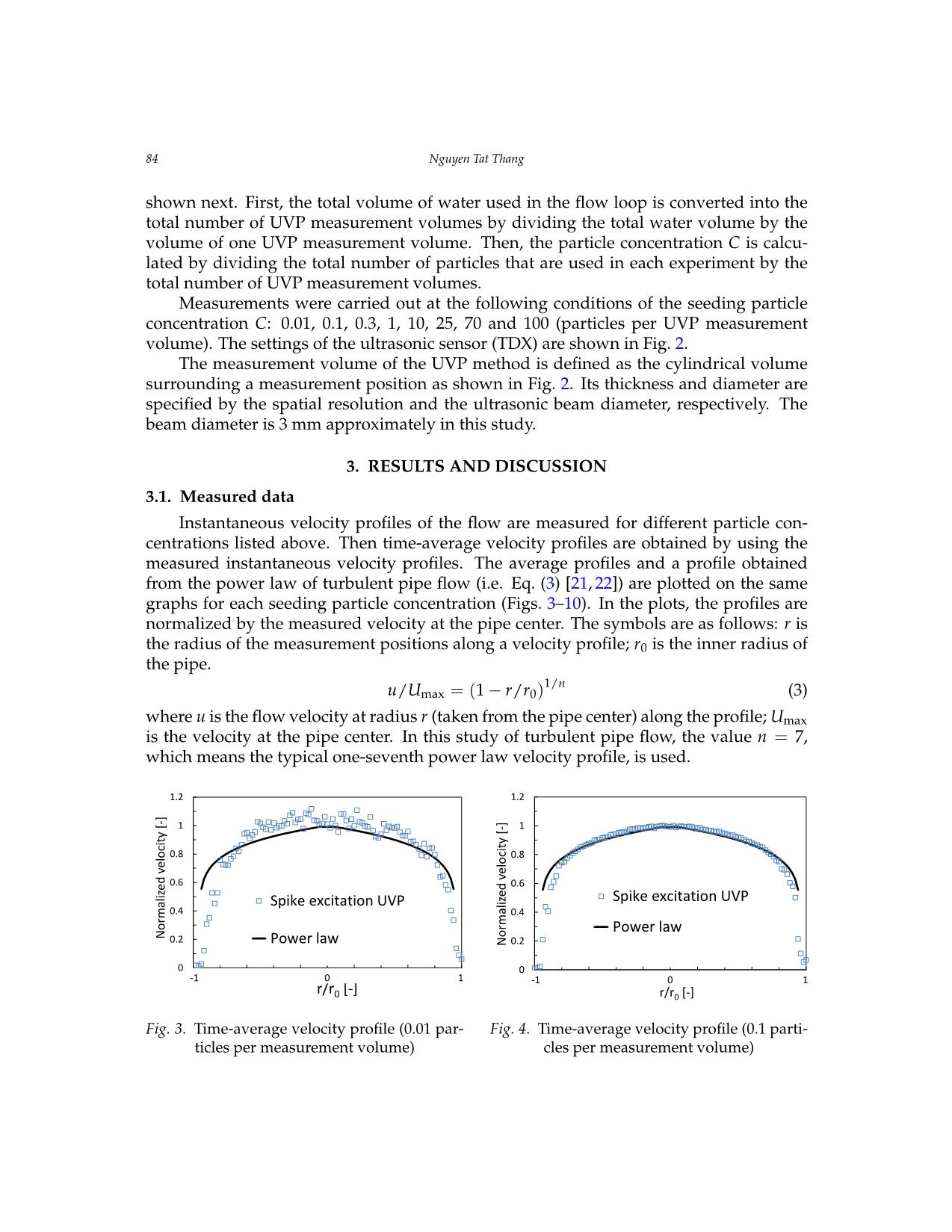
 As C increases, the SNR increases accordingly, the measured instantaneous velocity
profiles improve. The averaged velocity profiles become better. They are in good agree-
ment with that of the power law as seen in from Fig.4( C = 0.1) to 8 (C = 25). As general,
closer to the sensor, the measured averaged velocity fits better to the theoretical profile
since the SNR in such area is higher. Thus the corresponding instantaneous data should
also be reliable. And the SNR in such range of C and of the measurement depth (i.e. the
distance along the sound path starting from the sensor surface) could be appropriate for
the measurements, particularly in this investigation.
 Since the UVP method is a non-intrusive and profile measurement method, the max-
imum measurable depth where the flow velocity can still be measured correctly is also a
useful parameter. One of the main factors influencing the parameter is the particle con-
centration. As C increases, the maximum measurable depth of the UVP method increases
accordingly. However, this tendency is only applicable up to some value of the seeding-
particle concentration. Up to some higher value, the maximum measurable depth de-
creases since the sound attenuation appears to play an important role when the particle
concentration is high. Sound is attenuated strongly and its strength abruptly decreases at
some distance from the sensor surface. The same problem applies to the backscattered ul-
trasound from the seeding particles. The sensor receives very weak signal returning from
the flow field. Investigation of the phenomenon in the UVP method is also of interest.
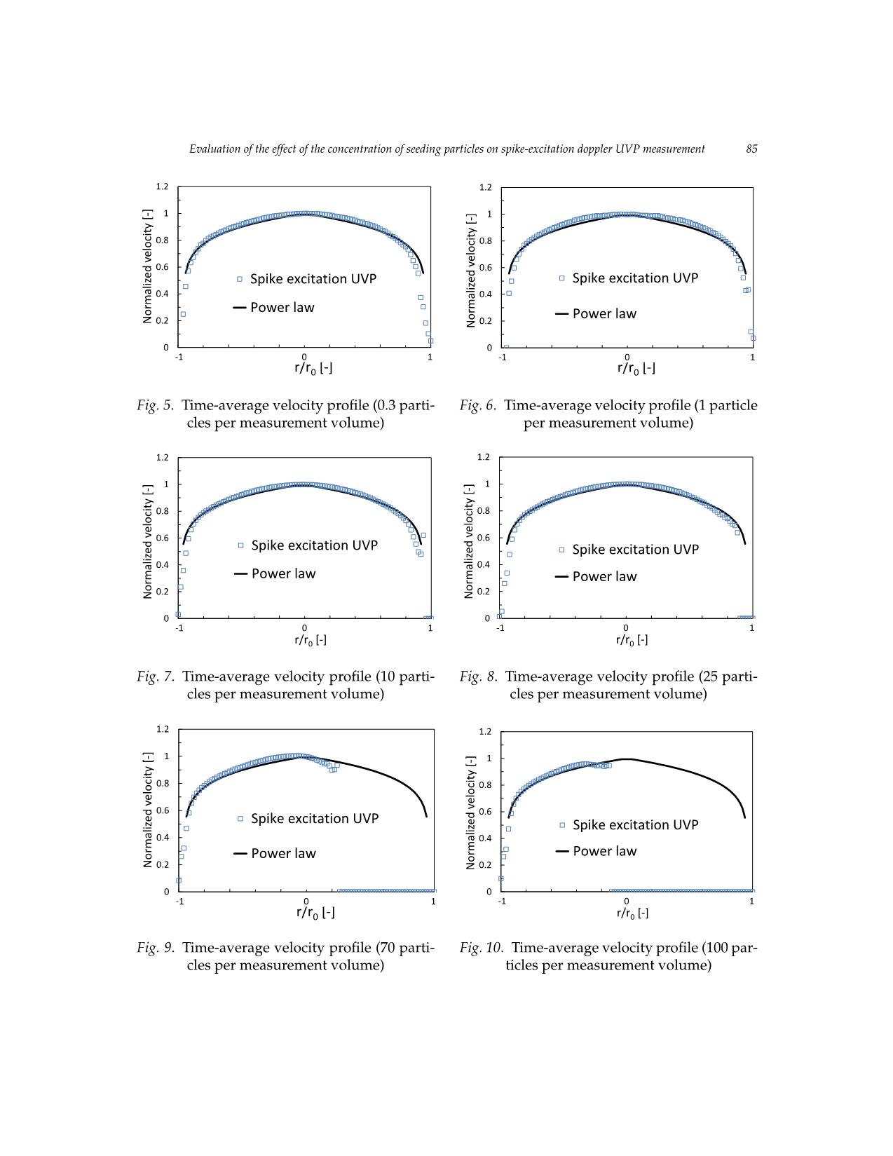
 As can be observed in Figs.4 to8, in the far distance of the velocity profiles, the
measured velocity first improves when C increases from 0.1 to 1 (Figs.4 to6). The most
appropriate velocity profile would be the one measured around C = 1. Further increas-
ing C, the measured data do not improve accordingly as can be seen in Figs.7 and8.
 At increased C (Figs.9 and 10), the sound attenuation problem becomes obvious. The
measured data are affected more strongly as C increases. Beyond some critical depth,
the measured velocity all becomes zero, but not noise as in the cases of low seeding
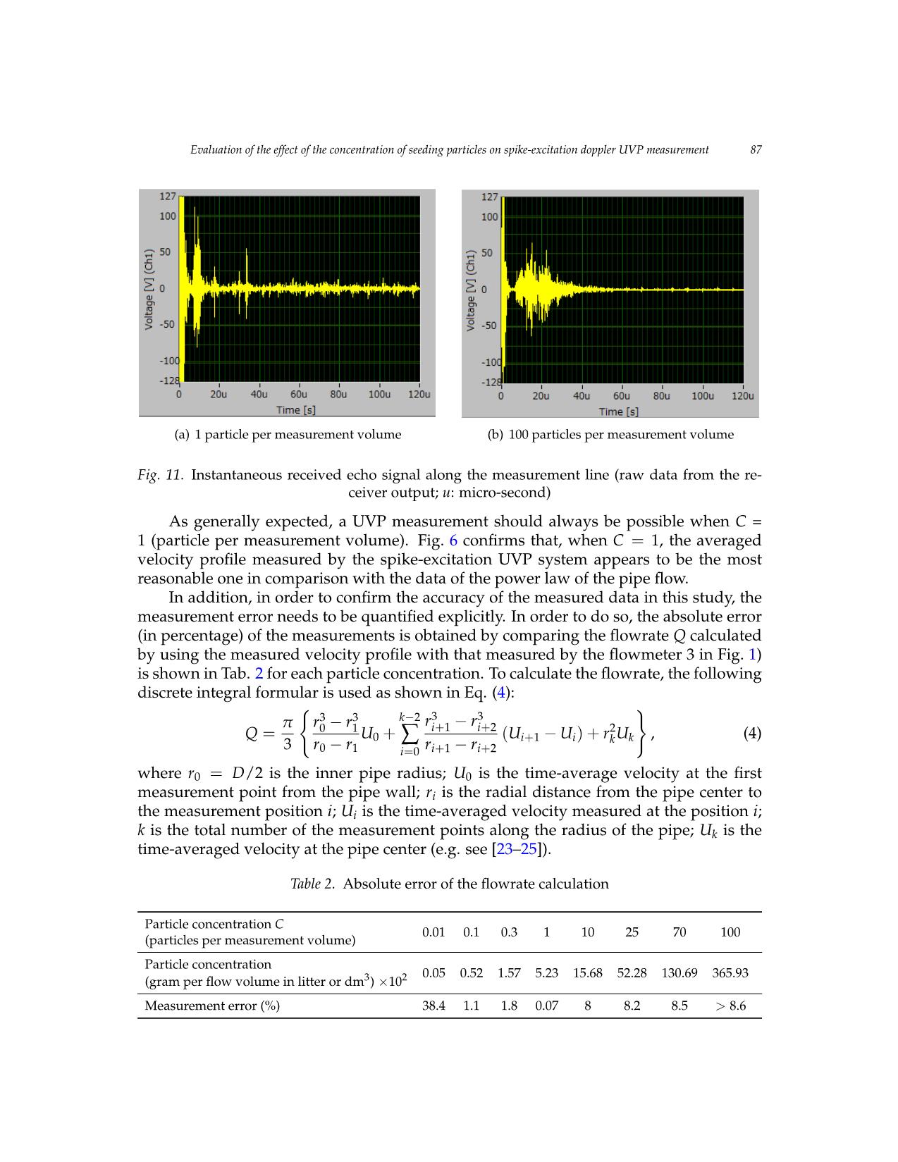
particle concentration. It is useful to look at the received echo signal, i.e. the raw signal
before applying signal processing, as briefly shown in Figs. 11(a) and 11(b). When C = 1
(Fig. 11(a)), the echo signal distributes fairly along the measurement line. However, when
C = 100 (Fig. 11(b)), it is obvious that the signal strength is high in the close part of the
profile but degenerates quickly in the far distance.
 a) 1 particle per measurement volume
 Evaluation of the effect of the concentration of seeding particles on spike-excitation doppler UVP measurement 87
 (a) 1 particle per measurement volume (b) 100 particles per measurement volume
 a) 1 particle per measurement volume b) 100 particles per measurement volume
 Fig. 11. Instantaneous received echo signal along the measurement line (raw data from the re-
 Figure 11. Instantaneous received echo signal along the measurement line (raw data from the receiver output; u:
 ceiver output; u: micro-second)
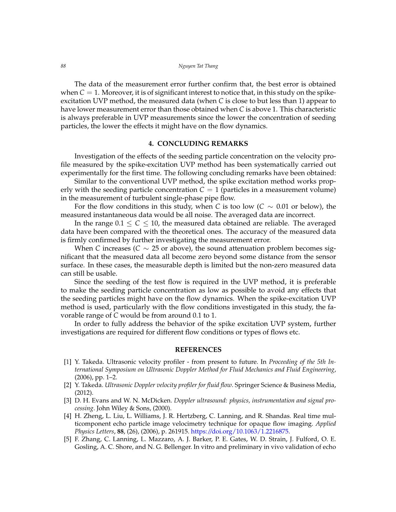
 As generally expected, a UVP measurement should alwaysmicro- besecond). possible when C =
 1 (particle per measurement volume). Fig.6 confirms that, when C = 1, the averaged
 velocity profile measuredAs generally by expected, the spike-excitation a UVP measurement UVP should system always appears be possible to bewhen the C = most 1 (particle per measurement volume).
 reasonable one in comparison with the data of the power law of the pipe flow.
 In addition, inFigure order 6 to confirms confirm that, the when accuracy C = 1, of the the averaged measured velocity data profile in this measured study, by the the spike-excitation UVP system
 measurement errorappears needs to to be be the quantified most reasonable explicitly. one in comparison In order towith do the so, data the of absolutethe power law error of the pipe flow.
 (in percentage) of the measurements is obtained by comparing the flowrate Q calculated
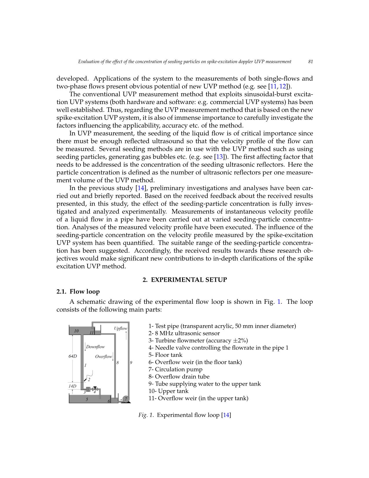
 by using the measured velocity profile with that measured by the flowmeter 3 in Fig.1)
 In addition, in order to confirm the accuracy of the measured data in this study, the measurement error needs to be
 is shown in Tab.2 for each particle concentration. To calculate the flowrate, the following
 discrete integral formularquantified is explicitly. used as In shown order to in do Eq. so, (the4): absolute error (in percentage) of the measurements is obtained by comparing
 ( )
 π r3 − r3 k−2 r3 − r3
 Q =the flowrate0 Q 1calculatedU + byi +using1 thei+ 2measu(U red− velocityU ) + profr2Uile with, that measured (4) by the flowmeter 3 in Figure 1) is
 − 0 ∑ − i+1 i k k
 3 r0 r1 i=0 ri+1 ri+2
 shown in Table 2 for each particle concentration. To calculate the flowrate, the following discrete integral formular is
 whereb) 10r00 =particlesD/2 per is m theeasurement inner pipevolume radius; U0 is the time-average velocity at the first
 measurement pointused from as shown the pipe in Equation wall; (r4i):is the radial distance from the pipe center to
Figure 11. Instantaneous receivedthe measurementecho signal along positionthe measurementi; Ui is line the (raw time-averaged data from the receiver velocity output; measured u: at the position i;
 k is the total number of the measurement points along the radius of the pipe; Uk is the
 time-averaged velocitymicro-second). at the pipe center (e.g. see [23–25]).
As generally expected, a UVP measurement should always beTable possible 2. Absolute when C = error 1 (particle of the per flowrate measurement calculation volume)11 .
Figure 6 confirms that, when C =Particle 1, the concentration averaged velocityC profile measured by the spike-excitation UVP system
 0.01 0.1 0.3 1 10 25 70 100
 (particles per measurement volume)
appears to be the most reasonable one in comparison with the data of the power law of the pipe flow.
 Particle concentration
 0.05 0.52 1.57 5.23 15.68 52.28 130.69 365.93
 (gram per flow volume in litter or dm3) ×102
In addition, in order to confirm the accuracy of the measured data in this study, the measurement error needs to be
 Measurement error (%) 38.4 1.1 1.8 0.07 8 8.2 8.5 > 8.6
quantified explicitly. In order to do so, the absolute error (in percentage) of the measurements is obtained by comparing
the flowrate Q calculated by using the measured velocity profile with that measured by the flowmeter 3 in Figure 1) is
shown in Table 2 for each particle concentration. To calculate the flowrate, the following discrete integral formular is
used as shown in Equation (4):
 11
88 Nguyen Tat Thang
 The data of the measurement error further confirm that, the best error is obtained
when C = 1. Moreover, it is of significant interest to notice that, in this study on the spike-
excitation UVP method, the measured data (when C is close to but less than 1) appear to
have lower measurement error than those obtained when C is above 1. This characteristic
is always preferable in UVP measurements since the lower the concentration of seeding
particles, the lower the effects it might have on the flow dynamics.
 4. CONCLUDING REMARKS
 Investigation of the effects of the seeding particle concentration on the velocity pro-
file measured by the spike-excitation UVP method has been systematically carried out
experimentally for the first time. The following concluding remarks have been obtained:
 Similar to the conventional UVP method, the spike excitation method works prop-
erly with the seeding particle concentration C = 1 (particles in a measurement volume)
in the measurement of turbulent single-phase pipe flow.
 For the flow conditions in this study, when C is too low (C ∼ 0.01 or below), the
measured instantaneous data would be all noise. The averaged data are incorrect.
 In the range 0.1 ≤ C ≤ 10, the measured data obtained are reliable. The averaged
data have been compared with the theoretical ones. The accuracy of the measured data
is firmly confirmed by further investigating the measurement error.
 When C increases (C ∼ 25 or above), the sound attenuation problem becomes sig-
nificant that the measured data all become zero beyond some distance from the sensor
surface. In these cases, the measurable depth is limited but the non-zero measured data
can still be usable.
 Since the seeding of the test flow is required in the UVP method, it is preferable
to make the seeding particle concentration as low as possible to avoid any effects that
the seeding particles might have on the flow dynamics. When the spike-excitation UVP
method is used, particularly with the flow conditions investigated in this study, the fa-
vorable range of C would be from around 0.1 to 1.
 In order to fully address the behavior of the spike excitation UVP system, further
investigations are required for different flow conditions or types of flows etc.
 REFERENCES
 [1] Y. Takeda. Ultrasonic velocity profiler - from present to future. In Proceeding of the 5th In-
 ternational Symposium on Ultrasonic Doppler Method for Fluid Mechanics and Fluid Engineering,
 (2006), pp. 1–2.
 [2] Y. Takeda. Ultrasonic Doppler velocity profiler for fluid flow. Springer Science & Business Media,
 (2012).
 [3] D. H. Evans and W. N. McDicken. Doppler ultrasound: physics, instrumentation and signal pro-
 cessing. John Wiley & Sons, (2000).
 [4] H. Zheng, L. Liu, L. Williams, J. R. Hertzberg, C. Lanning, and R. Shandas. Real time mul-
 ticomponent echo particle image velocimetry technique for opaque flow imaging. Applied
 Physics Letters, 88, (26), (2006), p. 261915. https://doi.org/10.1063/1.2216875.
 [5] F. Zhang, C. Lanning, L. Mazzaro, A. J. Barker, P. E. Gates, W. D. Strain, J. Fulford, O. E.
 Gosling, A. C. Shore, and N. G. Bellenger. In vitro and preliminary in vivo validation of echo
 Evaluation of the effect of the concentration of seeding particles on spike-excitation doppler UVP measurement 89
 particle image velocimetry in carotid vascular imaging. Ultrasound in Medicine & Biology, 37,
 (3), (2011), pp. 450–464. https://doi.org/10.1016/j.ultrasmedbio.2010.11.017.
 [6] H. Yu, M. Leeser, G. Tadmor, and S. Siegel. Real-time particle image velocimetry for feedback
 loops using FPGA implementation. Journal of Aerospace Computing, Information, and Commu-
 nication, 3, (2), (2006), pp. 52–62. https://doi.org/10.2514/1.18062.
 [7] T. T. Nguyen, H. Kikura, N. H. Duong, H. Murakawa, and N. Tsuzuki. Measurements of
 single-phase and two-phase flows in a vertical pipe using ultrasonic pulse Doppler method
 and ultrasonic time-domain cross-correlation method. Vietnam Journal of Mechanics, 35, (3),
 (2013), pp. 239–256. https://doi.org/10.15625/0866-7136/35/3/3070.
 [8] M. J. W. Povey. Ultrasonic techniques for fluids characterization. Elsevier, (1997).
 [9] P. J. Shull. Nondestructive evaluation: theory, techniques, and applications. CRC Press, (2002).
[10] T. T. Nguyen. Study of ultrasonic velocity profiling method on boiling two-phase flow. PhD thesis,
 Tokyo Institute of Technology, Tokyo, Japan, (2016).
[11] T. T. Nguyen, N. Tsuzuki, H. Murakawa, N. H. Duong, and H. Kikura. Measurement of
 the condensation rate of vapor bubbles rising upward in subcooled water by using two ul-
 trasonic frequencies. International Journal of Heat and Mass Transfer, 99, (2016), pp. 159–169.
 https://doi.org/10.1016/j.ijheatmasstransfer.2016.03.109.
[12] T. T. Nguyen, H. Kikura, H. Murakawa, and N. Tsuzuki. Measurement of bub-
 bly two-phase flow in vertical pipe using multiwave ultrasonic pulsed Dopller
 method and wire mesh tomography. Energy Procedia, 71, (2015), pp. 337–351.
 https://doi.org/10.1016/j.egypro.2014.11.887.
[13] B. Birkhofer, T. Meile, G. De Cesare, S. A. K. Jeelani, and E. J. Windhab. Use of gas bubbles
 for ultrasound Doppler flow velocity profile measurement. Flow Measurement and Instrumen-
 tation, 52, (2016), pp. 233–239. https://doi.org/10.1016/j.flowmeasinst.2016.10.015.
[14] N. T. Thang. Two advanced non-intrusive methods for velocity distribution measurement
 in fluid mechanics with some recent research and development. In Proceedings of the Interna-
 tional Conference of Fluid Machinery and Automation Systems - ICFMAS2018, (2018), pp. 653–
 661.
[15] D. W. Baker. Pulsed ultrasonic Doppler blood-flow sensing. IEEE Transactions on Sonics and
 Ultrasonics, 17, (3), (1975), pp. 170–185.
[16] Y. Takeda. Velocity profile measurement by ultrasound Doppler shift method. International
 Journal of Heat and Fluid Flow, 7, (4), (1986), pp. 313–318. https://doi.org/10.1016/0142-
 727x(86)90011-1.
[17] J. A. Jensen. Estimation of blood velocities using ultrasound: a signal processing approach. Cam-
 bridge University Press, (1996).
[18] T. T. Nguyen, H. Murakawa, N. Tsuzuki, H. N. Duong, and H. Kikura. Ultrasonic Doppler
 velocity profile measurement of single-and two-phase flows using spike excitation. Experi-
 mental Techniques, 40, (4), (2016), pp. 1235–1248. https://doi.org/10.1007/s40799-016-0123-8.
[19] H. Murakawa. Study on ultrasonic measurement technique for flow structure in bubbly flow. PhD
 thesis, Tokyo Institute of Technology, Tokyo, Japan, (2006).
[20] T. T. Nguyen, H. Murakawa, N. Tsuzuki, and H. Kikura. Development of multi-
 wave method using ultrasonic pulse Doppler method for measuring two-phase flow.
 Journal of the Japanese Society for Experimental Mechanics, 13, (3), (2013), pp. 277–284.
 https://doi.org/10.11395/jjsem.13.277.
[21] P. K. Kundu, I. M. Cohen, and H. H. Hu. Fluid mechanics. Elsevier Academic Press, (2008).
90 Nguyen Tat Thang
[22] L. J. De Chant. The venerable 1/7th power law turbulent velocity profile: a clas-
 sical nonlinear boundary value problem solution and its relationship to stochas-
 tic processes. Applied Mathematics and Computation, 161, (2), (2005), pp. 463–474.
 https://doi.org/10.1016/j.amc.2003.12.109.
[23] S. Wada, H. Kikura, M. Aritomi, M. Mori, and Y. Takeda. Development of pulse ultrasonic
 Doppler method for flow rate measurement in power plant multilines flow rate measure-
 ment on metal pipe. Journal of Nuclear Science and Technology, 41, (3), (2004), pp. 339–346.
 https://doi.org/10.1080/18811248.2004.9715493.
[24] Y. Inoue, H. Kikura, H. Murakawa, M. Aritomi, and M. Mori. A study of ultrasonic propa-
 gation for ultrasonic flow rate measurement. Flow Measurement and Instrumentation, 19, (3-4),
 (2008), pp. 223–232. https://doi.org/10.1016/j.flowmeasinst.2007.06.013.
[25] W. Treenuson, N. Tsuzuki, H. Kikura, M. Aritomi, S. Wada, and K. Tezuka. Accurate
 flowrate measurement on the double bent pipe using ultrasonic velocity profile method.
 Journal of the Japanese Society for Experimental Mechanics, 13, (2), (2013), pp. 200–211.
 https://doi.org/10.11395/jjsem.13.200.
File đính kèm:
 evaluation_of_the_effect_of_the_concentration_of_seeding_par.pdf

