Dynamics and control of a four - bar mechanism with relative longitudinal vibration of the coupler link
Traditionally, dynamic analysis and control of
mechanisms have been based on the assumption that
the links behave as rigid bodies. The demand for high
speed lightweight machinery requires a redesign of
the current mechanisms. Unfortunately, reducing the
weight of four-bar mechanisms and/or increasing
their speed may lead to the onset of elastic
oscillations, which causes performance degradations
such as misfeeding in the case of the card feeder
mechanism in Sandor et al [1]. Therefore, the
dynamic analysis and control vibration of flexible
mechanisms are required. Although dynamic analysis
of flexible mechanisms has been the subject of
numerous investigations [1-6], the control of such
systems has not received much attention [2-4]. Most
of the work available in the literature which deals
with vibration control of flexible mechanisms employ
an actuator which acts directly on the flexible link.
The effect of the control forces and moments on the
overall motion is neglected. An alternative method
would be to control the vibrations through the motion
of the input link.
The current study deals with the control of a
four-bar mechanism with a flexible coupler link. An
actuator is assumed to be placed on the input link
which applies a control torque. A simple PD control
is designed which requires measurements of the
position and angular velocity of the input link only.
2. Equations of motion of the four-bar mechanism
* Corresponding author: Tel.: (+84) 977.244.292
Email: nam.nguyensy@gmail.com
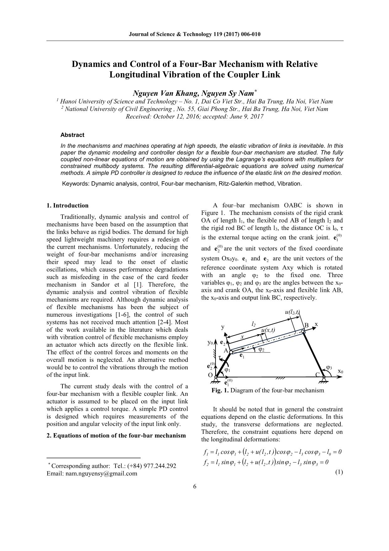
A four–bar mechanism OABC is shown in
Figure 1. The mechanism consists of the rigid crank
OA of length l1, the flexible rod AB of length l2 and
the rigid rod BC of length l3, the distance OC is l0, τ
is the external torque acting on the crank joint. e1(0)
and (0)
e2 are the unit vectors of the fixed coordinate
system Ox0y0. e1 and e2 are the unit vectors of the
reference coordinate system Axy which is rotated
with an angle φ2 to the fixed one. Three
variables φ1, φ2 and φ3 are the angles between the x0-
axis and crank OA, the x0-axis and flexible link AB,
the x0-axis and output link BC, respectively.
It should be noted that in general the constraint
equations depend on the elastic deformations. In this
study, the transverse deformations are neglected.
Therefore, the constraint equations here depend on
the longitudinal deformations:
f l sin l u( l ,t )sin l sin 0
f l cos l u( l ,t ) cos l cos l 0
2 1 1 2 2 2 3 3
1 1 1 2 2 2 3 3 0
(1)
O
A
B
φ1
y0
φ2
φ3
C x0
τ
Fig. 1. Diagram of the four-bar mechanism
x
y l2
(0
Trang 1
Trang 2
Trang 3
Trang 4
Trang 5
Tóm tắt nội dung tài liệu: Dynamics and control of a four - bar mechanism with relative longitudinal vibration of the coupler link
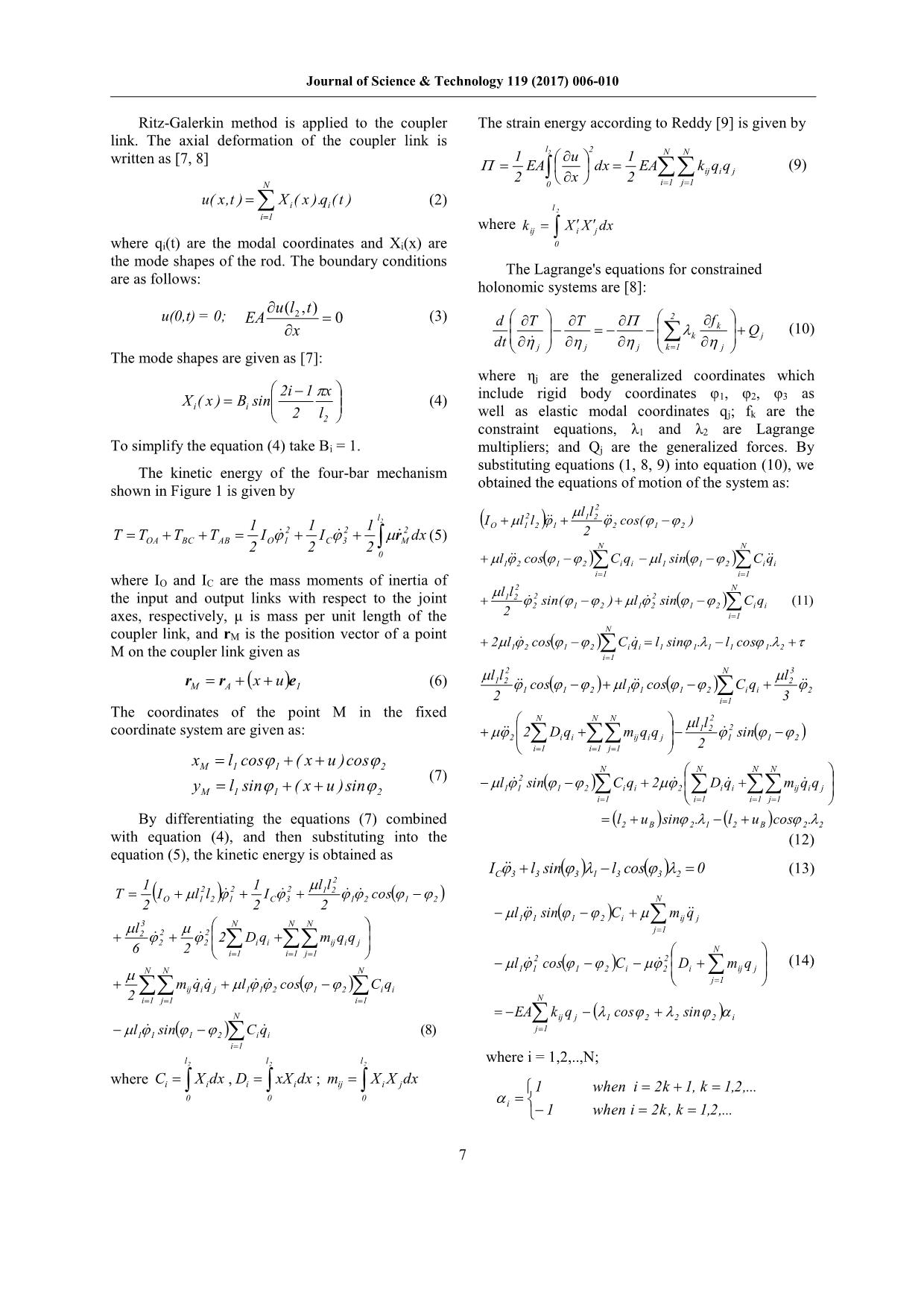
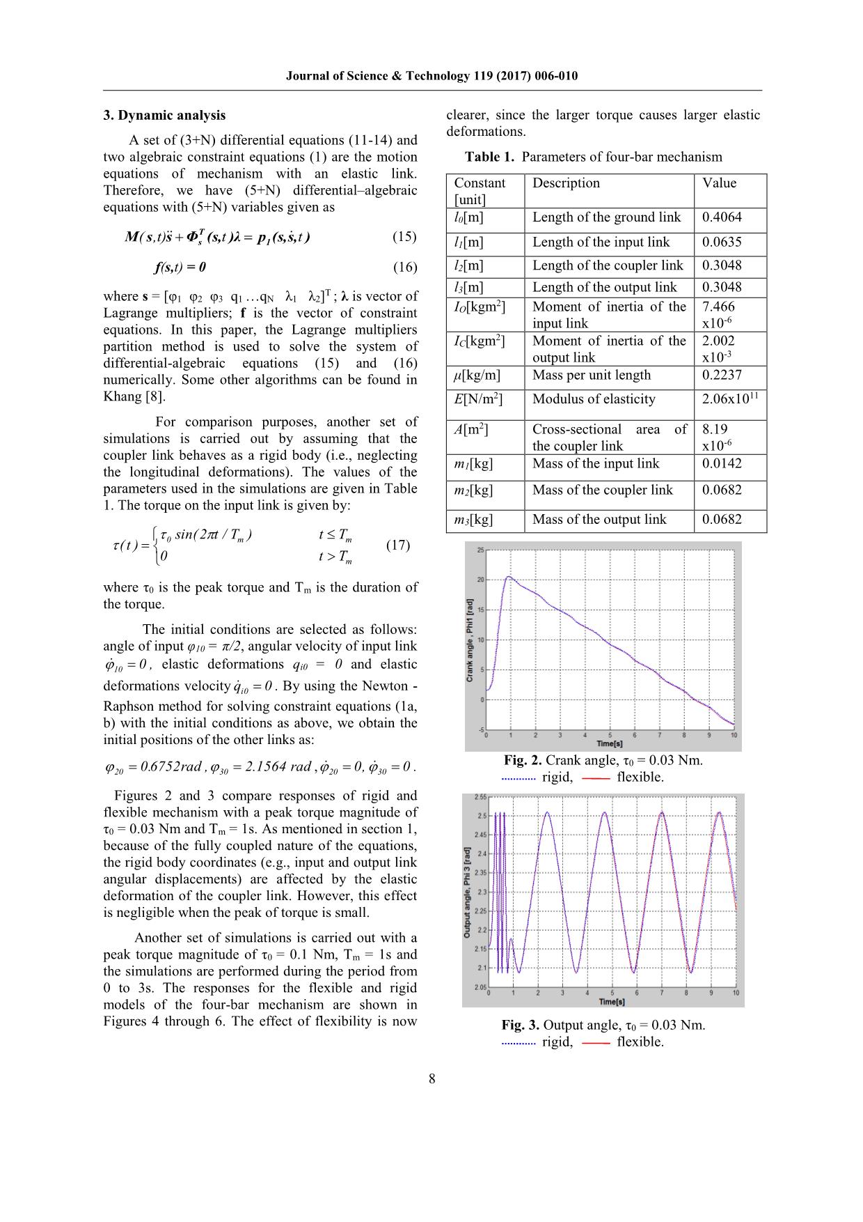
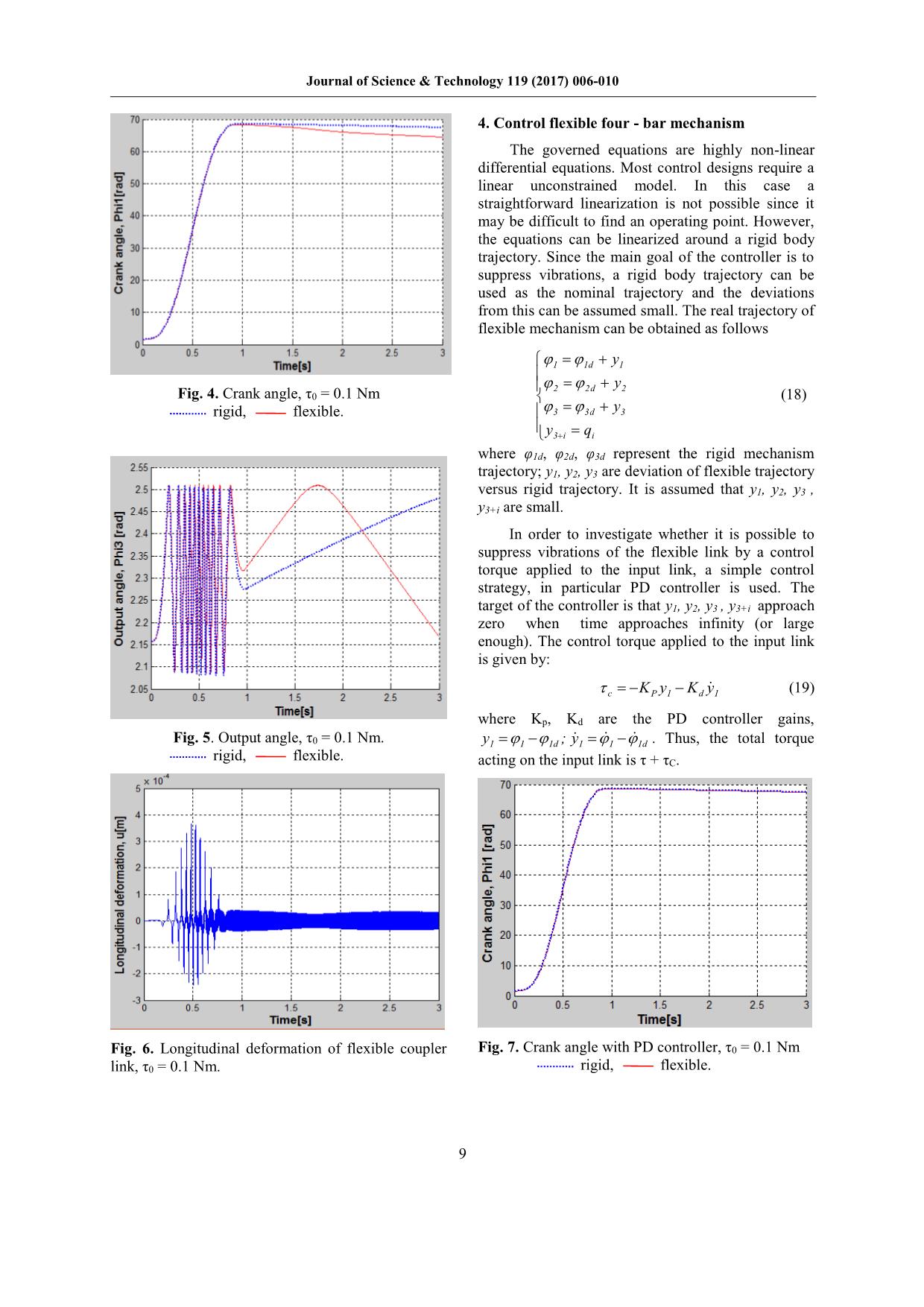
Journal of Science & Technology 119 (2017) 006-010 Dynamics and Control of a Four-Bar Mechanism with Relative Longitudinal Vibration of the Coupler Link Nguyen Van Khang, Nguyen Sy Nam* 1 Hanoi University of Science and Technology – No. 1, Dai Co Viet Str., Hai Ba Trung, Ha Noi, Viet Nam 2 National University of Civil Engineering , No. 55, Giai Phong Str., Hai Ba Trung, Ha Noi, Viet Nam Received: October 12, 2016; accepted: June 9, 2017 Abstract In the mechanisms and machines operating at high speeds, the elastic vibration of links is inevitable. In this paper the dynamic modeling and controller design for a flexible four-bar mechanism are studied. The fully coupled non-linear equations of motion are obtained by using the Lagrange’s equations with multipliers for constrained multibody systems. The resulting differential-algebraic equations are solved using numerical methods. A simple PD controller is designed to reduce the influence of the elastic link on the desired motion. Keywords: Dynamic analysis, control, Four-bar mechanism, Ritz-Galerkin method, Vibration. 1. Introduction * A four–bar mechanism OABC is shown in Figure 1. The mechanism consists of the rigid crank Traditionally, dynamic analysis and control of OA of length l , the flexible rod AB of length l and mechanisms have been based on the assumption that 1 2 the rigid rod BC of length l , the distance OC is l , τ the links behave as rigid bodies. The demand for high 3 0 (0) speed lightweight machinery requires a redesign of is the external torque acting on the crank joint. e1 the current mechanisms. Unfortunately, reducing the (0) and e2 are the unit vectors of the fixed coordinate weight of four-bar mechanisms and/or increasing system Ox y . e and e are the unit vectors of the their speed may lead to the onset of elastic 0 0 1 2 oscillations, which causes performance degradations reference coordinate system Axy which is rotated such as misfeeding in the case of the card feeder with an angle φ2 to the fixed one. Three mechanism in Sandor et al [1]. Therefore, the variables φ1, φ2 and φ3 are the angles between the x0- dynamic analysis and control vibration of flexible axis and crank OA, the x0-axis and flexible link AB, mechanisms are required. Although dynamic analysis the x0-axis and output link BC, respectively. of flexible mechanisms has been the subject of numerous investigations [1-6], the control of such u(l2,t) systems has not received much attention [2-4]. Most y l2 B x of the work available in the literature which deals u(x,t) with vibration control of flexible mechanisms employ x an actuator which acts directly on the flexible link. y0 e2 A φ2 The effect of the control forces and moments on the e overall motion is neglected. An alternative method τ 1 (0) would be to control the vibrations through the motion e2 φ3 φ1 x0 of the input link. O C e(0) The current study deals with the control of a 1 Fig. 1. Diagram of the four-bar mechanism four-bar mechanism with a flexible coupler link. An actuator is assumed to be placed on the input link which applies a control torque. A simple PD control It should be noted that in general the constraint is designed which requires measurements of the equations depend on the elastic deformations. In this position and angular velocity of the input link only. study, the transverse deformations are neglected. Therefore, the constraint equations here depend on 2. Equations of motion of the four-bar mechanism the longitudinal deformations: f1 l1 cos 1 l2 u( l2 ,t ) cos 2 l3 cos 3 l0 0 f l sin l u( l ,t ) sin l sin 0 * Corresponding author: Tel.: (+84) 977.244.292 2 1 1 2 2 2 3 3 Email: nam.nguyensy@gmail.com (1) 6 Journal of Science & Technology 119 (2017) 006-010 Ritz-Galerkin method is applied to the coupler The strain energy according to Reddy [9] is given by link. The axial deformation of the coupler link is l 2 written as [7, 8] 1 2 u 1 N N EA dx EA k q q (9) 2 x 2 ij i j N 0 i 1 j 1 u( x,t ) X ( x ).q ( t ) (2) i i l 2 i 1 where k X X dx ij i j where qi(t) are the modal coordinates and Xi(x) are 0 the mode shapes of the rod. The boundary conditions The Lagrange's equations for constrained are as follows: holonomic systems are [8]: u(l ,t) u(0,t) = 0; EA 2 0 (3) d T T 2 f x k Q (10) k j dt j j j k 1 j The mode shapes are given as [7]: where ηj are the generalized coordinates which 2i 1 x X ( x ) B sin (4) include rigid body coordinates φ1, φ2, φ3 as i i well as elastic modal coordinates q ; f are the 2 l2 j k constraint equations, λ1 and λ2 are Lagrange To simplify the equation (4) take Bi = 1. multipliers; and Qj are the generalized forces. By substituting equations (1, 8, 9) into equation (10), we The kinetic energy of the four-bar mechanism obtained the equations of motion of the system as: shown in Figure 1 is given by 2 l 2 l1l2 2 I l l cos( ) 1 2 1 2 1 2 O 1 2 1 2 2 1 2 T TOA TBC TAB IO 1 IC 3 rM dx (5) 2 2 2 N N 0 l1 2 cos 1 2 Ci qi l1 sin 1 2 Ci qi i 1 i 1 where IO and IC are the mass moments of inertia of l l 2 N the input and output links with respect to the joint 1 2 2 2 2 sin( 1 2 ) l1 2 sin 1 2 Ci qi (11) axes, respectively, μ is mass per unit length of the 2 i 1 N coupler link, and rM is the position vector of a point 2l1 2 cos 1 2 Ci qi l1 sin 1.1 l1 cos 1.2 M on the coupler link given as i 1 l l 2 N l 3 r r x u e (6) 1 2 2 M A 1 1 cos 1 2 l1 1 cos 1 2 Ci qi 2 2 i 1 3 The coordinates of the point M in the fixed N N N l l 2 coordinate system are given as: 2 D q m q q 1 2 2 sin 2 i i ij i j 1 1 2 i 1 i 1 j 1 2 x l cos ( x u )cos M 1 1 2 N N N N (7) l 2 sin C q 2 D q m q q yM l1 sin 1 ( x u )sin 2 1 1 1 2 i i 2 i i ij i j i 1 i 1 i 1 j 1 By differentiating the equations (7) combined l2 uB sin 2.1 l2 uB cos 2.2 with equation (4), and then substituting into the (12) equation (5), the kinetic energy is obtained as IC 3 l3 sin 3 1 l3 cos 3 2 0 (13) 1 1 l l 2 T I l 2l 2 I 2 1 2 cos 2 O 1 2 1 2 C 3 2 1 2 1 2 N l1 1 sin 1 2 Ci mij q j 3 N N N l j 1 2 2 2 2 2 2 Di qi mij qi q j N 6 2 i 1 i 1 j 1 l 2 cos C 2 D m q (14) N N N 1 1 1 2 i 2 i ij j j 1 mij qi q j l1 1 2 cos 1 2 Ci qi 2 i 1 j 1 i 1 N N EA kij q j 1 cos 2 2 sin 2 i j 1 l1 1 sin 1 2 Ci qi (8) i 1 l2 l2 l2 where i = 1,2,..,N; where C X dx , D xX dx ; m X X dx i i i i ij i j 1 when i 2k 1, k 1,2,... 0 0 0 i 1 when i 2k, k 1,2,... 7 Journal of Science & Technology 119 (2017) 006-010 3. Dynamic analysis clearer, since the larger torque causes larger elastic deformations. A set of (3+N) differential equations (11-14) and two algebraic constraint equations (1) are the motion Table 1. Parameters of four-bar mechanism equations of mechanism with an elastic link. Constant Description Value Therefore, we have (5+N) differential–algebraic [unit] equations with (5+N) variables given as l0[m] Length of the ground link 0.4064 M( s,t)s ΦT (s,t )λ p (s,s,t ) (15) s 1 l1[m] Length of the input link 0.0635 f(s,t) = 0 (16) l2[m] Length of the coupler link 0.3048 T l3[m] Length of the output link 0.3048 where s = [φ1 φ2 φ3 q1 qN λ1 λ2] ; λ is vector of 2 IO[kgm ] Moment of inertia of the 7.466 Lagrange multipliers; f is the vector of constraint -6 equations. In this paper, the Lagrange multipliers input link x10 2 partition method is used to solve the system of IC[kgm ] Moment of inertia of the 2.002 -3 differential-algebraic equations (15) and (16) output link x10 numerically. Some other algorithms can be found in μ[kg/m] Mass per unit length 0.2237 Khang [8]. E[N/m2] Modulus of elasticity 2.06x10¹¹ For comparison purposes, another set of A[m2] Cross-sectional area of 8.19 simulations is carried out by assuming that the the coupler link x10-6 coupler link behaves as a rigid body (i.e., neglecting m [kg] Mass of the input link 0.0142 the longitudinal deformations). The values of the 1 parameters used in the simulations are given in Table m2[kg] Mass of the coupler link 0.0682 1. The torque on the input link is given by: m3[kg] Mass of the output link 0.0682 0 sin(2 t / Tm ) t Tm (t ) (17) 0 t Tm where τ0 is the peak torque and Tm is the duration of the torque. The initial conditions are selected as follows: angle of input φ10 = π/2, angular velocity of input link 10 0 , elastic deformations qi0 = 0 and elastic deformations velocity qi0 0 . By using the Newton - Raphson method for solving constraint equations (1a, b) with the initial conditions as above, we obtain the initial positions of the other links as: 0.6752rad , 2.1564 rad , 0, 0 . Fig. 2. Crank angle, τ0 = 0.03 Nm. 20 30 20 30 rigid, flexible. Figures 2 and 3 compare responses of rigid and flexible mechanism with a peak torque magnitude of τ0 = 0.03 Nm and Tm = 1s. As mentioned in section 1, because of the fully coupled nature of the equations, the rigid body coordinates (e.g., input and output link angular displacements) are affected by the elastic deformation of the coupler link. However, this effect is negligible when the peak of torque is small. Another set of simulations is carried out with a peak torque magnitude of τ0 = 0.1 Nm, Tm = 1s and the simulations are performed during the period from 0 to 3s. The responses for the flexible and rigid models of the four-bar mechanism are shown in Figures 4 through 6. The effect of flexibility is now Fig. 3. Output angle, τ0 = 0.03 Nm. rigid, flexible. 8 Journal of Science & Technology 119 (2017) 006-010 4. Control flexible four - bar mechanism The governed equations are highly non-linear differential equations. Most control designs require a linear unconstrained model. In this case a straightforward linearization is not possible since it may be difficult to find an operating point. However, the equations can be linearized around a rigid body trajectory. Since the main goal of the controller is to suppress vibrations, a rigid body trajectory can be used as the nominal trajectory and the deviations from this can be assumed small. The real trajectory of flexible mechanism can be obtained as follows 1 1d y1 2 2d y2 Fig. 4. Crank angle, τ0 = 0.1 Nm (18) rigid, flexible. 3 3d y3 y q 3 i i where φ1d, φ2d, φ3d represent the rigid mechanism trajectory; y1, y2, y3 are deviation of flexible trajectory versus rigid trajectory. It is assumed that y1, y2, y3 , y3+i are small. In order to investigate whether it is possible to suppress vibrations of the flexible link by a control torque applied to the input link, a simple control strategy, in particular PD controller is used. The target of the controller is that y1, y2, y3 , y3+i approach zero when time approaches infinity (or large enough). The control torque applied to the input link is given by: c KP y1 Kd y1 (19) where Kp, Kd are the PD controller gains, Fig. 5. Output angle, τ0 = 0.1 Nm. y1 1 1d ; y1 1 1d . Thus, the total torque rigid, flexible. acting on the input link is τ + τC. Fig. 6. Longitudinal deformation of flexible coupler Fig. 7. Crank angle with PD controller, τ0 = 0.1 Nm link, τ0 = 0.1 Nm. rigid, flexible. 9 Journal of Science & Technology 119 (2017) 006-010 numerically to simulate the system behavior. A simple PD controller was designed which does not require measurement of the elastic deformations. The controller has been shown to be efficient in suppressing the vibrations of the flexible link as well as controlling the rigid body motion. References [1] Sandor, G. N. and Erdman, A. G. (1984) Advanced Mechanism Design: Analysis and Synthesis. Englewood Cliffs, NJ: Prentice-Hall. [2] Sung, C. K. and Chen, Y. C (1991) Vibration control of the elastodynamic response of high-speed flexible linkage mechanisms. ASME Journal of Vibration and Acoustics 113, 14-21. Fig. 8. Output angle with PD controller. τ0 = 0.1 Nm. rigid, flexible. [3] Beale, D. G. and Lee, S. W. (1995) The applicability of fuzzy control for flexible mechanisms. ASME Design Engineering Technical Conferences DE-Vol. 84-1, 203-209. [4] Liao, W. H. Chou, J. H. and Horng, I. R (1997). Robust vibration control of flexible linkage mechanisms using piezoelectric films. Smart Materials and Structures 6, 457-463. [5] Schwab, A. L. and Meijard, J. P. (1997) Small vibrations superim - Posedon non-linear rigid body motion. Proceedings of the 1997 ASME Design Engineering Technical Conferences, Sacramento, CA,1-7. [6] Yigit, A. Scott, R.A. and Ulsoy, A.G (1988), “Flexural motion of aradially rotating beam attached to a rigid body”. Journal of Sound and Vibration 121, 201 - 210. [7] Khang, N.V (2005), Engineering vibrations (in Fig. 9. Longitudinal deformation of flexible coupler Vietnamese), Science and Technics Publishing House link with PD controller, τ = 0.1 Nm. 0 [8] Khang, N.V (2017), Dynamic of multibody system (in rigid, flexible. Vietnamese, 2. Edition) Science and Technics Now, we will suppress vibrations in case the Publishing House. peak torque magnitude of τ0 = 0.1 Nm and Tm = 1s [9] Reddy, J.N (2002), Energy Principles and Variational (e.g., Figures 4 – 6). The parameters used in the Methods in Applied Mechanics, John Wiley and Son, simulations are given in Table 1. The controller gains ISBN: 978-0-471-17985-6. are chosen as K = 0.5, K = 0.2. The calculating p d [10] Bajodah, A. H. Hodges, D. H. and Chen, Y. H (2003) results are shown in Figs 7 – 9. These “New form of Kane’s equations for constrained results show that controller is able to suppress the systems”. Journal of Guidance, Control, and Dynamics vibrations and control the link angular motions. In 26:79–88. Figure 9 the longitudinal deformation is suppressed within 0.85 s. 5. Conclusions In this study, dynamic modeling and control of a four-bar mechanism with flexible coupler link has been investigated and it was assumed that there is only axial deformation. The non-linear equations of motion are obtained through a constrained Lagrangian approach and described by a set of differential-algebraic equations. The governed differential-algebraic equations are solved 10
File đính kèm:
 dynamics_and_control_of_a_four_bar_mechanism_with_relative_l.pdf

