Analysis of linear elastic fracture mechanics for cracked functionally graded composite plate by enhanced local enriched consecutive - Interpolation elements
This paper reports the application of consecutive-interpolation procedure into four-node
quadrilateral elements for analysis of two-dimensional cracked solids made of functionally graded
composite plate. Compared to standard finite element method, the recent developed consecutiveinterpolation has been shown to possess many desirable features, such as higher accuracy and
smooth nodal gradients it still satisfies the Kronecker-delta property and keeps the total number of
degrees of freedom unchanged. The discontinuity in displacement fields along the crack faces and
stress singularity around the crack tips are mathematically modeled using enrichment functions. The
Heaviside function is employed to describe displacement jump, while four branch functions being
developed from asymptotic stress fields are taken as basis functions to capture singularities. The
interesting characteristic of functionall graded composite plate is the spatial variation of material
properties which are intentionally designed to be served for particular purposes. Such variation has
to be taken into account during the computation of Stress Intensity Factors (SIFs). Performance of
the proposed approach is demonstrated and verified through various numerical examples, in which
SIFs are compared with reference solutions derived from other methods available in literatures.
Trang 1
Trang 2
Trang 3
Trang 4
Trang 5
Trang 6
Trang 7
Trang 8
Trang 9
Trang 10
Tải về để xem bản đầy đủ
Tóm tắt nội dung tài liệu: Analysis of linear elastic fracture mechanics for cracked functionally graded composite plate by enhanced local enriched consecutive - Interpolation elements
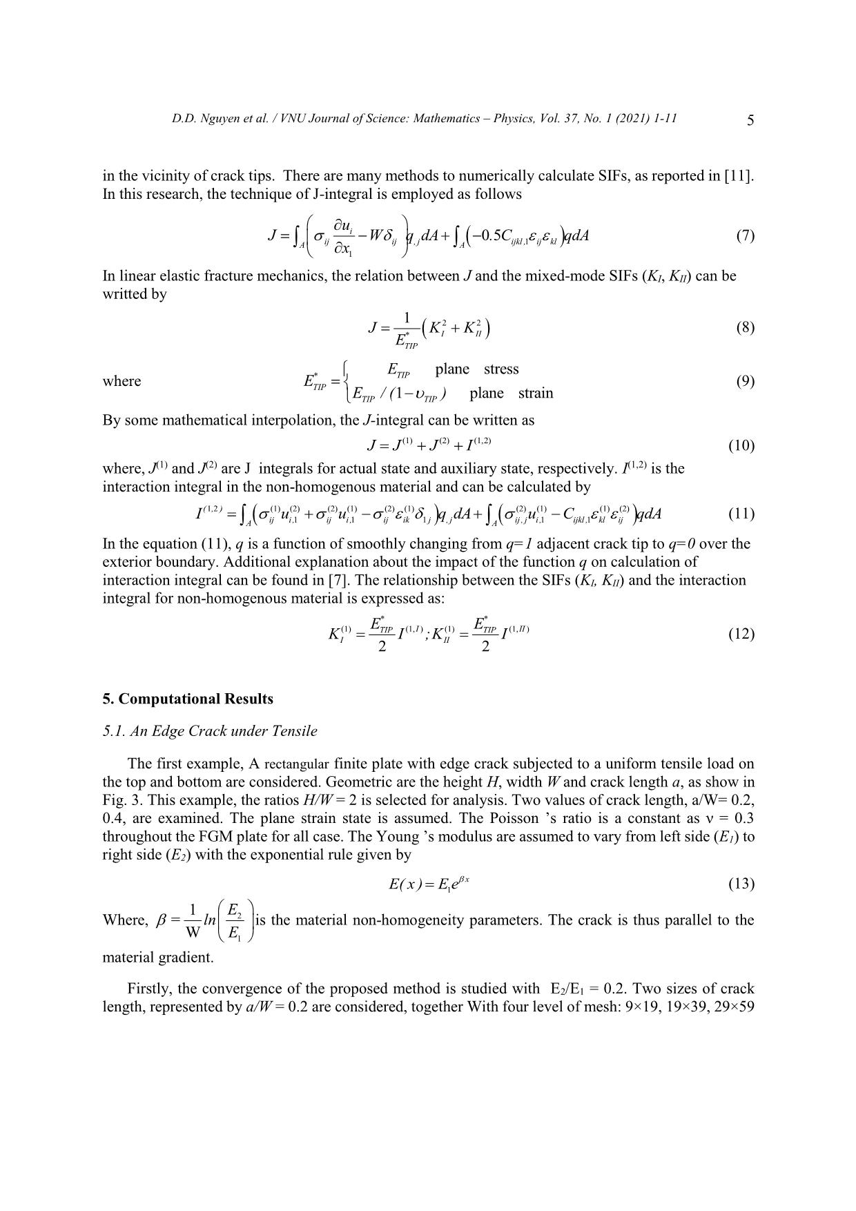
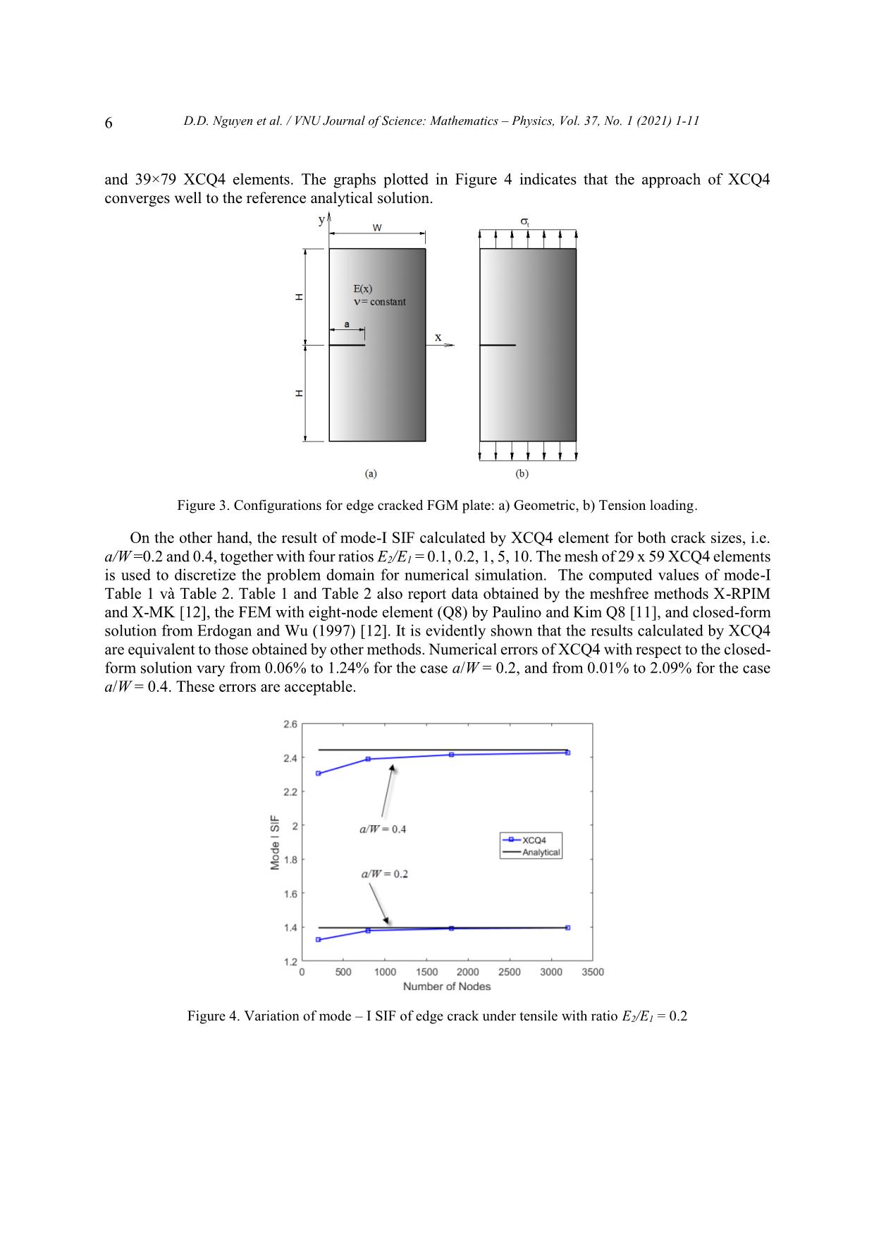
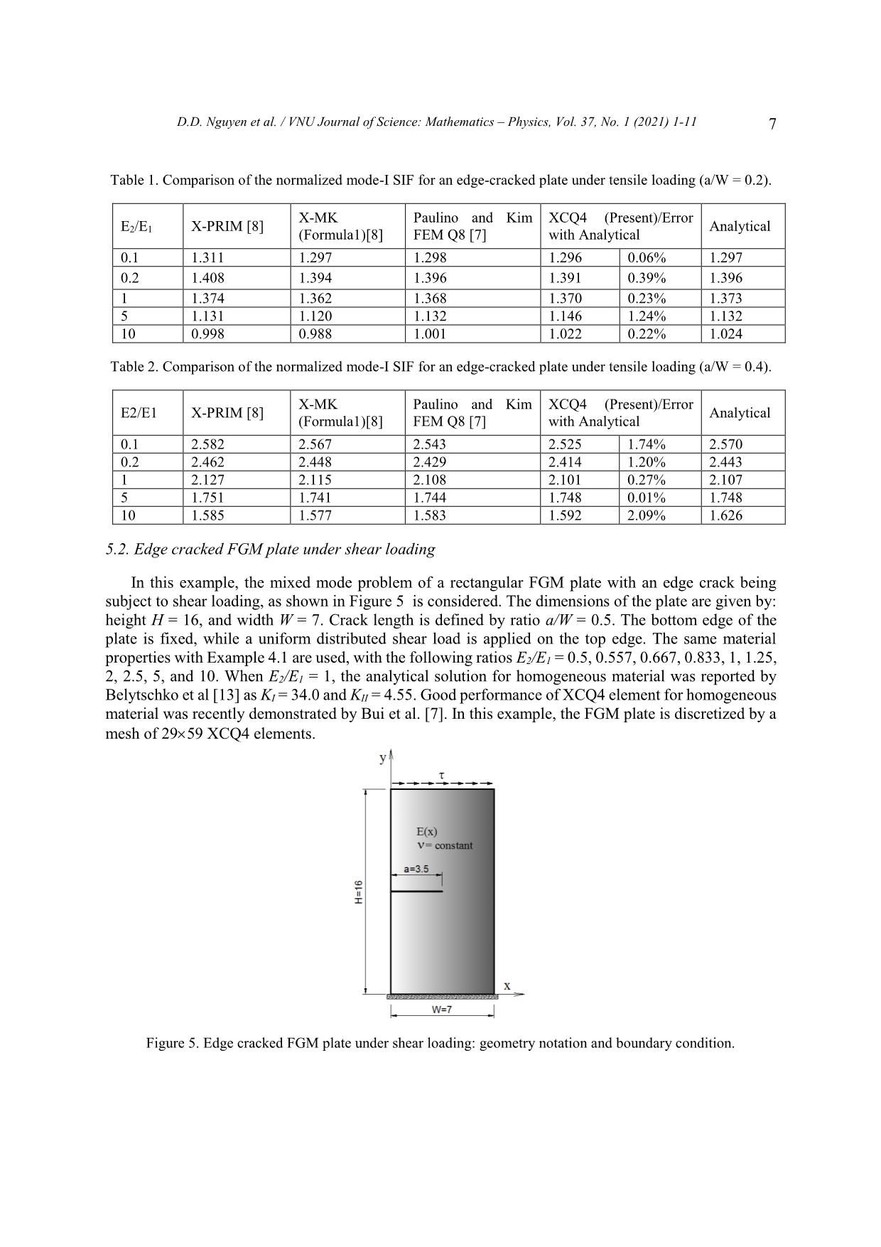
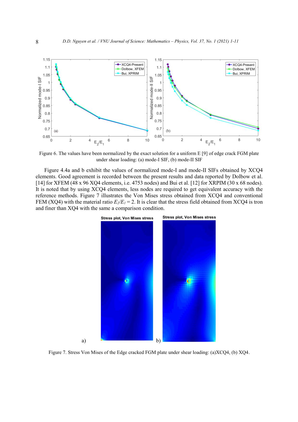
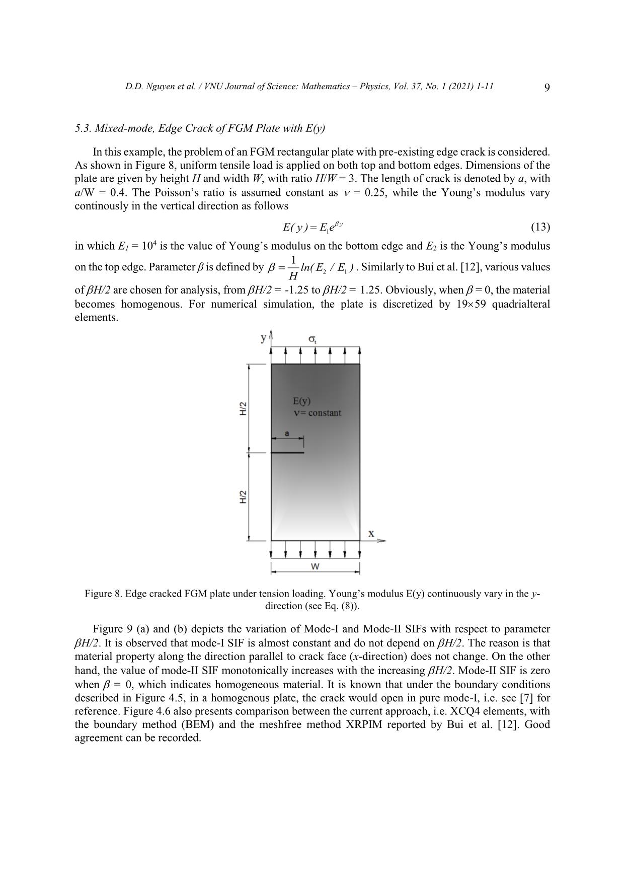
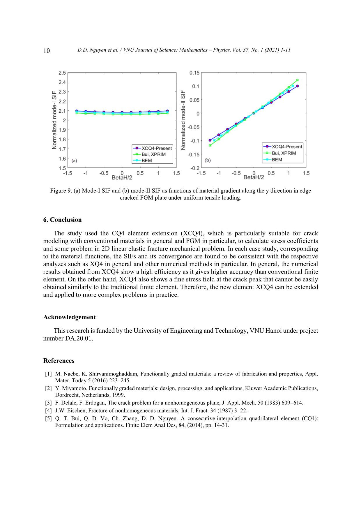
VNU Journal of Science: Mathematics – Physics, Vol. 37, No. 1 (2021) 1-11 Original Article Analysis of Linear Elastic Fracture Mechanics for Cracked Functionally Graded Composite Plate by Enhanced Local Enriched Consecutive-interpolation Elements Dinh Du Nguyen1,2,*, Dinh Duc Nguyen2, Quoc Tinh Bui3 1Lac Hong University, Dong Nai, Vietnam 2VNU University of Engineering and Technology, 144 Xuan Thuy, Cau Giay, Hanoi, Viet Nam 3Tokyo Institute of Technology, 2-12-1-W8-22, Ookayama, Meguro-ku, Tokyo 152-8552, Japan Received 03 March 2020 Revised 12 March 2020; Accepted 15 March 2020 Abstract. This paper reports the application of consecutive-interpolation procedure into four-node quadrilateral elements for analysis of two-dimensional cracked solids made of functionally graded composite plate. Compared to standard finite element method, the recent developed consecutive- interpolation has been shown to possess many desirable features, such as higher accuracy and smooth nodal gradients it still satisfies the Kronecker-delta property and keeps the total number of degrees of freedom unchanged. The discontinuity in displacement fields along the crack faces and stress singularity around the crack tips are mathematically modeled using enrichment functions. The Heaviside function is employed to describe displacement jump, while four branch functions being developed from asymptotic stress fields are taken as basis functions to capture singularities. The interesting characteristic of functionall graded composite plate is the spatial variation of material properties which are intentionally designed to be served for particular purposes. Such variation has to be taken into account during the computation of Stress Intensity Factors (SIFs). Performance of the proposed approach is demonstrated and verified through various numerical examples, in which SIFs are compared with reference solutions derived from other methods available in literatures. Keywords: Dynamic stress intensity factors, Consecutive-interpolation procedure XFEM, Composite materials FEM, cracked FGM composite plate. ________ Corresponding author. Email address: dinhdu85@gmail.com https//doi.org/ 10.25073/2588-1124/vnumap.4632 1 2 D.D. Nguyen et al. / VNU Journal of Science: Mathematics – Physics, Vol. 37, No. 1 (2021) 1-11 1. Introduction Nowadays, composite materials have gained much attraction due to the growing applications in many fields including aeronautical, transportation, defense engineering, nuclear energy, electronics, optics, biomaterials, and energy conversion .etc [1, 2]. However, during working conditions, the development of crack formation is inevitable. In designing components involving FGMs, it is crucially important to consider imperfections, such as flaws, defects, and cracks, which are typically formed during the growth processes or generated by external loads during service. Fracture mechanics of FGMs, particularly their dynamic failures, thus plays a central role in the design of FGMs structures in order to improve the service quality as well as the duration life of the FGM structures. The simulation and computational modeling of structures containing cracks have risen as important and challenging tasks in risk management. Currently, thanks to advanced technology in computer sciences, many commercial softwares have offerered packages for computational fracture mechanics based on Finite Element Method, which enable engineers to solve complicated problems which cannot be done by analytical means. FGM materials are characterized by the distinguishing feature of nonhomogeneity to thermomechanical properties and structural strength. Nevertheless, the stress field near the crack tip of FGM material for any form of elastic modulus variation is the same as homogeneous materials [3, 4]. The singular stress field accumulates strain energy at the crack-tip area is the cause to initiate the fracture in the structure. Therefore, it is not the maximum stress at a single point but the stress strength of the constant singularity field adjacent to the crack tip, i.e. the stress strength coefficients (SIFs), which determine the initiation of crack. Therefore, the proposed methods of calculating SIFs are important in the FGM. In this study, a novel numerical approach is proposed based on Extended Finite Element Method (XFEM) being enhanced by consecutive-interpolation procedure (CIP) [5, 6], in order to model the behaviour of physical fields in the vicinity of crack tips. Here, we focus on two-dimensional bodies made of Funtionally Graded Materials (FGM). Particularly, the concept of enriched functions which is quite familiar in XFEM is employed to mathematically capture the jump of displacement across crack surface and the singularity of stress surrounding crack tips. The traditional XFEM-based four-node ... in Figure 2. The difference between the CIP- enhanced element and the traditional finite element is visibly shown in Figure 2, such that the CIP- based shape function is smooth across nodes. Figure 1. Sketch of supporting nodes for an arbitrary point x located within a CQ4 element. 4 D.D. Nguyen et al. / VNU Journal of Science: Mathematics – Physics, Vol. 37, No. 1 (2021) 1-11 Figure 2. Shape functions of (a) Q4 element and (b) CQ4 element. 3. The XCQ4 element for plate made by functionally graded materials (FGM) The fundamental idea in Extended Finite Element Method (XFEM) is to capture the jump in displacement and singularity of stress fields in the vicinity of crack tips by the incorporation of enriched terms into the approximated displacement. With the utilization of enrichment approach, the CQ4 element is extended as XCQ4 element, in which the displacement can be approximated by h ~ ~ u (x) Ni (x)ui N j (x)H(x) H(x j )a j i I S j J cut 4 (5) ~ Nk (x)F (x) F (xk )bk k K tip 1 ~ cut In equation (5), Ni (x) denotes the CQ4 shape function associated with node I; J í the set of nodes belong the elements which are completely cut by the cracks; Ktip is the set of nodes belong to the elements containing crack tips; ui is the vector of nodal displacement at node i. Here H(x) is the Heaviside function which returns the sign of the signed distance value from point x to the crack segment; aj and bk are the additional degrees of freedom associated with the enriched terms. The four branch functions F (x) ( = 1, 2, 3, 4) are adopted from reference [7]. r sin 2 r cos 2 , (6) F (x)( 1 , 2 , 3 , 4 ) r sin sin 2 r cos sin 2 where (r,) is the local polar coordinate system defined at the crack center. 4. Stress Intensity Factors (SIFs) computation in FGM plates In analysis of cracked plate, including both homogeneous and non-homogeneous materials, it is important to determine the SIFs, which are fracture parameters being characteristics for the stress fields D.D. Nguyen et al. / VNU Journal of Science: Mathematics – Physics, Vol. 37, No. 1 (2021) 1-11 5 in the vicinity of crack tips. There are many methods to numerically calculate SIFs, as reported in [11]. In this research, the technique of J-integral is employed as follows u J i W q dA 05 . C qdA (7) AA ij ij , j ijkl ,1 ij kl x1 In linear elastic fracture mechanics, the relation between J and the mixed-mode SIFs (KI, KII) can be writted by 1 22 JKK * I II (8) ETIP * ETIP plane stress where ETIP (9) E/()TIP1 TIP plane strain By some mathematical interpolation, the J-integral can be written as JJJI (1) (2) (1,2) (10) where, J(1) and J(2) are J integrals for actual state and auxiliary state, respectively. I(1,2) is the interaction integral in the non-homogenous material and can be calculated by I(,)1 2 (1) u (2) (2) u (1) (2) (1) qdA (2) uC (1) (1) (2) qdA (11) AA ij i,1 ij i, 1 ij ik 1 j , j ij , j i, 1 ijkl , 1 kl ij In the equation (11), q is a function of smoothly changing from q=1 adjacent crack tip to q=0 over the exterior boundary. Additional explanation about the impact of the function q on calculation of interaction integral can be found in [7]. The relationship between the SIFs (KI, KII) and the interaction integral for non-homogenous material is expressed as: EE** KI;KI(1) TIP (1,I ) (1) TIP (1, II ) (12) I22 II 5. Computational Results 5.1. An Edge Crack under Tensile The first example, A rectangular finite plate with edge crack subjected to a uniform tensile load on the top and bottom are considered. Geometric are the height H, width W and crack length a, as show in Fig. 3. This example, the ratios H/W = 2 is selected for analysis. Two values of crack length, a/W= 0.2, 0.4, are examined. The plane strain state is assumed. The Poisson ’s ratio is a constant as ν = 0.3 throughout the FGM plate for all case. The Young ’s modulus are assumed to vary from left side (E1) to right side (E2) with the exponential rule given by E( x ) E e x (13) 1 1 E Where, = ln 2 is the material non-homogeneity parameters. The crack is thus parallel to the W E1 material gradient. Firstly, the convergence of the proposed method is studied with E2/E1 = 0.2. Two sizes of crack length, represented by a/W = 0.2 are considered, together With four level of mesh: 9×19, 19×39, 29×59 6 D.D. Nguyen et al. / VNU Journal of Science: Mathematics – Physics, Vol. 37, No. 1 (2021) 1-11 and 39×79 XCQ4 elements. The graphs plotted in Figure 4 indicates that the approach of XCQ4 converges well to the reference analytical solution. Figure 3. Configurations for edge cracked FGM plate: a) Geometric, b) Tension loading. On the other hand, the result of mode-I SIF calculated by XCQ4 element for both crack sizes, i.e. a/W =0.2 and 0.4, together with four ratios E2/E1 = 0.1, 0.2, 1, 5, 10. The mesh of 29 x 59 XCQ4 elements is used to discretize the problem domain for numerical simulation. The computed values of mode-I Table 1 và Table 2. Table 1 and Table 2 also report data obtained by the meshfree methods X-RPIM and X-MK [12], the FEM with eight-node element (Q8) by Paulino and Kim Q8 [11], and closed-form solution from Erdogan and Wu (1997) [12]. It is evidently shown that the results calculated by XCQ4 are equivalent to those obtained by other methods. Numerical errors of XCQ4 with respect to the closed- form solution vary from 0.06% to 1.24% for the case a/W = 0.2, and from 0.01% to 2.09% for the case a/W = 0.4. These errors are acceptable. Figure 4. Variation of mode – I SIF of edge crack under tensile with ratio E2/E1 = 0.2 D.D. Nguyen et al. / VNU Journal of Science: Mathematics – Physics, Vol. 37, No. 1 (2021) 1-11 7 Table 1. Comparison of the normalized mode-I SIF for an edge-cracked plate under tensile loading (a/W = 0.2). X-MK Paulino and Kim XCQ4 (Present)/Error E /E X-PRIM [8] Analytical 2 1 (Formula1)[8] FEM Q8 [7] with Analytical 0.1 1.311 1.297 1.298 1.296 0.06% 1.297 0.2 1.408 1.394 1.396 1.391 0.39% 1.396 1 1.374 1.362 1.368 1.370 0.23% 1.373 5 1.131 1.120 1.132 1.146 1.24% 1.132 10 0.998 0.988 1.001 1.022 0.22% 1.024 Table 2. Comparison of the normalized mode-I SIF for an edge-cracked plate under tensile loading (a/W = 0.4). X-MK Paulino and Kim XCQ4 (Present)/Error E2/E1 X-PRIM [8] Analytical (Formula1)[8] FEM Q8 [7] with Analytical 0.1 2.582 2.567 2.543 2.525 1.74% 2.570 0.2 2.462 2.448 2.429 2.414 1.20% 2.443 1 2.127 2.115 2.108 2.101 0.27% 2.107 5 1.751 1.741 1.744 1.748 0.01% 1.748 10 1.585 1.577 1.583 1.592 2.09% 1.626 5.2. Edge cracked FGM plate under shear loading In this example, the mixed mode problem of a rectangular FGM plate with an edge crack being subject to shear loading, as shown in Figure 5 is considered. The dimensions of the plate are given by: height H = 16, and width W = 7. Crack length is defined by ratio a/W = 0.5. The bottom edge of the plate is fixed, while a uniform distributed shear load is applied on the top edge. The same material properties with Example 4.1 are used, with the following ratios E2/E1 = 0.5, 0.557, 0.667, 0.833, 1, 1.25, 2, 2.5, 5, and 10. When E2/E1 = 1, the analytical solution for homogeneous material was reported by Belytschko et al [13] as KI = 34.0 and KII = 4.55. Good performance of XCQ4 element for homogeneous material was recently demonstrated by Bui et al. [7]. In this example, the FGM plate is discretized by a mesh of 29 59 XCQ4 elements. Figure 5. Edge cracked FGM plate under shear loading: geometry notation and boundary condition. 8 D.D. Nguyen et al. / VNU Journal of Science: Mathematics – Physics, Vol. 37, No. 1 (2021) 1-11 Figure 6. The values have been normalized by the exact solution for a uniform E [9] of edge crack FGM plate under shear loading: (a) mode-I SIF, (b) mode-II SIF Figure 4.4a and b exhibit the values of normalized mode-I and mode-II SIFs obtained by XCQ4 elements. Good agreement is recorded between the present results and data reported by Dolbow et al. [14] for XFEM (48 x 96 XQ4 elements, i.e. 4753 nodes) and Bui et al. [12] for XRPIM (30 x 68 nodes). It is noted that by using XCQ4 elements, less nodes are required to get equivalent accuracy with the reference methods. Figure 7 illustrates the Von Mises stress obtained from XCQ4 and conventional FEM (XQ4) with the material ratio E2/E1 = 2. It is clear that the stress field obtained from XCQ4 is tron and finer than XQ4 with the same a comparison condition. a) b) Figure 7. Stress Von Mises of the Edge cracked FGM plate under shear loading: (a)XCQ4, (b) XQ4. D.D. Nguyen et al. / VNU Journal of Science: Mathematics – Physics, Vol. 37, No. 1 (2021) 1-11 9 5.3. Mixed-mode, Edge Crack of FGM Plate with E(y) In this example, the problem of an FGM rectangular plate with pre-existing edge crack is considered. As shown in Figure 8, uniform tensile load is applied on both top and bottom edges. Dimensions of the plate are given by height H and width W, with ratio H/W = 3. The length of crack is denoted by a, with a/W = 0.4. The Poisson’s ratio is assumed constant as = 0.25, while the Young’s modulus vary continously in the vertical direction as follows E( y ) E e y (13) 1 4 in which E1 = 10 is the value of Young’s modulus on the bottom edge and E2 is the Young’s modulus 1 on the top edge. Parameter β is defined by ln( E / E ) . Similarly to Bui et al. [12], various values H 21 of H/2 are chosen for analysis, from H/2 = -1.25 to H/2 = 1.25. Obviously, when = 0, the material becomes homogenous. For numerical simulation, the plate is discretized by 19 59 quadrialteral elements. Figure 8. Edge cracked FGM plate under tension loading. Young’s modulus E(y) continuously vary in the y- direction (see Eq. (8)). Figure 9 (a) and (b) depicts the variation of Mode-I and Mode-II SIFs with respect to parameter H/2. It is observed that mode-I SIF is almost constant and do not depend on H/2. The reason is that material property along the direction parallel to crack face (x-direction) does not change. On the other hand, the value of mode-II SIF monotonically increases with the increasing H/2. Mode-II SIF is zero when = 0, which indicates homogeneous material. It is known that under the boundary conditions described in Figure 4.5, in a homogenous plate, the crack would open in pure mode-I, i.e. see [7] for reference. Figure 4.6 also presents comparison between the current approach, i.e. XCQ4 elements, with the boundary method (BEM) and the meshfree method XRPIM reported by Bui et al. [12]. Good agreement can be recorded. 10 D.D. Nguyen et al. / VNU Journal of Science: Mathematics – Physics, Vol. 37, No. 1 (2021) 1-11 Figure 9. (a) Mode-I SIF and (b) mode-II SIF as functions of material gradient along the y direction in edge cracked FGM plate under uniform tensile loading. 6. Conclusion The study used the CQ4 element extension (XCQ4), which is particularly suitable for crack modeling with conventional materials in general and FGM in particular, to calculate stress coefficients and some problem in 2D linear elastic fracture mechanical problem. In each case study, corresponding to the material functions, the SIFs and its convergence are found to be consistent with the respective analyzes such as XQ4 in general and other numerical methods in particular. In general, the numerical results obtained from XCQ4 show a high efficiency as it gives higher accuracy than conventional finite element. On the other hand, XCQ4 also shows a fine stress field at the crack peak that cannot be easily obtained similarly to the traditional finite element. Therefore, the new element XCQ4 can be extended and applied to more complex problems in practice. Acknowledgement This research is funded by the University of Engineering and Technology, VNU Hanoi under project number DA.20.01. References [1] M. Naebe, K. Shirvanimoghaddam, Functionally graded materials: a review of fabrication and properties, Appl. Mater. Today 5 (2016) 223–245. [2] Y. Miyamoto, Functionally graded materials: design, processing, and applications, Kluwer Academic Publications, Dordrecht, Netherlands, 1999. [3] F. Delale, F. Erdogan, The crack problem for a nonhomogeneous plane, J. Appl. Mech. 50 (1983) 609–614. [4] J.W. Eischen, Fracture of nonhomogeneous materials, Int. J. Fract. 34 (1987) 3–22. [5] Q. T. Bui, Q. D. Vo, Ch. Zhang, D. D. Nguyen. A consecutive-interpolation quadrilateral element (CQ4): Formulation and applications. Finite Elem Anal Des, 84, (2014), pp. 14-31. D.D. Nguyen et al. / VNU Journal of Science: Mathematics – Physics, Vol. 37, No. 1 (2021) 1-11 11 [6] Q. T. Bui, D. D. Nguyen, X. D. Zhang, S. Hirose, R. C. Batra. Analysis of 2-dimensional transient problems for linear elastic and piezoelectric structures using the consecutive-interpolation quadrilateral element (CQ4). Eur J Mech A/Solids, 58, (2016), pp. 1-19. [7] Z. Y. Kang, Q. T. Bui, D. D. Nguyen, T. Saitoh, S. Hirose. An extended consecutive interpolation quadrilateral element (XCQ4) applied to linear elastic fracture mechanics. Acta Mech, 226, (2015), pp. 3991–4015. [8] M.N. Nguyen, Q. T. Bui, T.T. Truong, et al. Enhanced nodal gradient 3D consecutive-interpolation tetrahedral element (CTH4) for heat transfer analysis. Int J Heat Mass Trans, 103, (2016), pp. 14–27. [9] Zuoyi Kang, Tinh Quoc Bui, Du Dinh Nguyen, Sohichi Hirose. Dynamic stationary crack analysis of isotropic solids and anisotropic composites by enhanced local enriched consecutive-interpolation elements. Compos struct, 180, (2017), pp. 221-233. [10] P.V. Jeyakarthikeyan, G. Subramanian, R. Yogeshwaran. An alternate stable midpoint quadrature to improve the element stiffness matrix of quadrilaterals for application of functionally graded materials (FGM). Computers and Structures, 178, (2017), pp. 71-87. [11] Kim Jeong-Ho, Paulino GH. Finite element evaluation of mixed mode stress intensity factors in functionally graded materials. Int. J. Numer. Meth. Engng, 53, (2002), pp. 1903–1935. [12] Tinh Quoc Bui, Nha Thanh Nguyen, Le Van Lich, Minh Ngoc Nguyen, Thien Tich Truong. Analysis of transient dynamic fracture parameters of cracked functionally graded composites by improved meshfree methods. Theor Appl Fract Mech, , (2017). [13] Moes, N., Dolbow, J., Belytschko, T. A finite element method for crack growth without remeshing. Int. J. Numer. Methods Eng. 46 (1999), pp. 131–150. [14] J.E. Dolbow, M. Gosz, On the computation of mixed-mode stress intensity factors in functionally graded materials, Int. J. Solids Struct. 39 (2002), pp. 2557 –2574.
File đính kèm:
 analysis_of_linear_elastic_fracture_mechanics_for_cracked_fu.pdf

