An enhanced control strategy of three - phase four - wire inverters under nonlinear load conditions
An enhanced nonlinear control technique based on a coordination between feedback
linearization (FBL) approach and sliding mode control (SMC) is proposed for a three-phase
split-capacitor inverter under the nonlinear load conditions. A nonlinear model of system with
pulse-width modulation (PWM) voltage-source inverter (VSI) including the output inductorcapacitor (LC) filters is derived in the d-q-0 synchronous reference frame, not by small signal
analysis. The controllers for d-q-0 components of three-phase line-to-neutral load voltages are
designed by linear control theory. With the proposed coordination scheme, three-phase
split-capacitor inverter provides an excellent control performance for regulating the load
voltages with nearly zero steady-state errors in both the transient and steady states. The proposed
scheme is verified by the simulation results which show that three-phase split-capacitor inverter
gives a low total harmonic distortion (THD) for the load voltages under the balanced or
unbalanced nonlinear load conditions.
Keywords: Nonlinear load, three-phase inverter, feedback linearization, sliding mode control,
unbalanced load.
Trang 1
Trang 2
Trang 3
Trang 4
Trang 5
Trang 6
Trang 7
Trang 8
Trang 9
Trang 10
Tải về để xem bản đầy đủ
Tóm tắt nội dung tài liệu: An enhanced control strategy of three - phase four - wire inverters under nonlinear load conditions
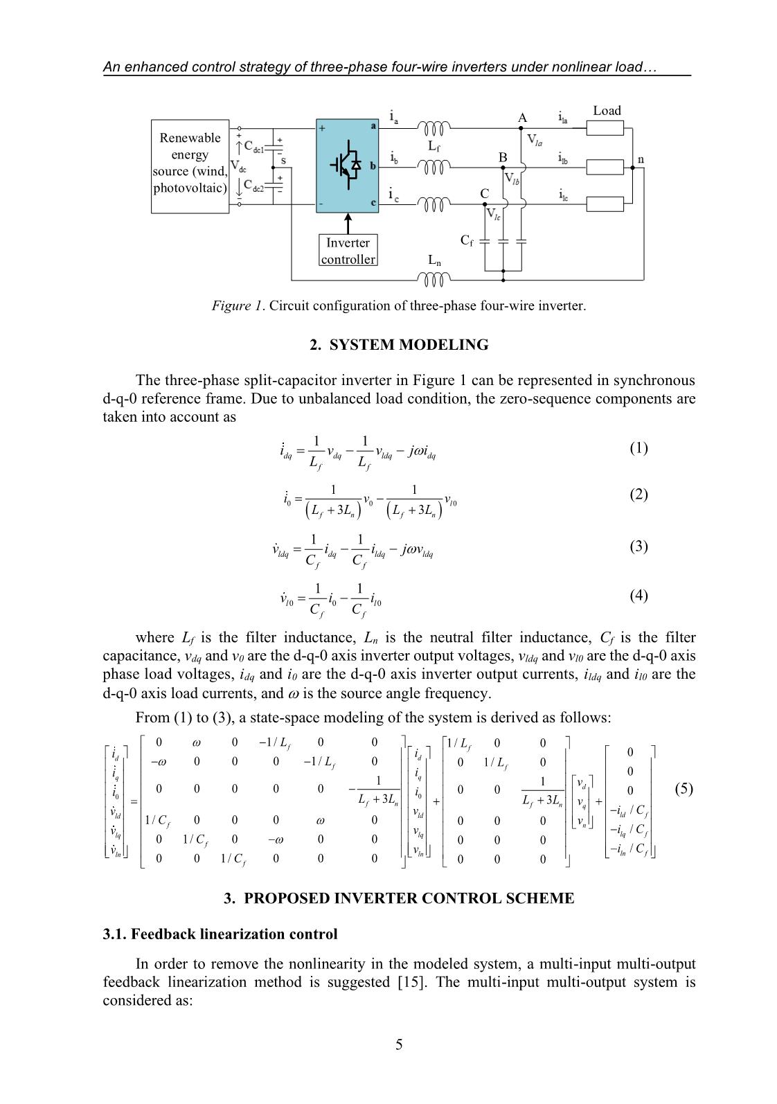
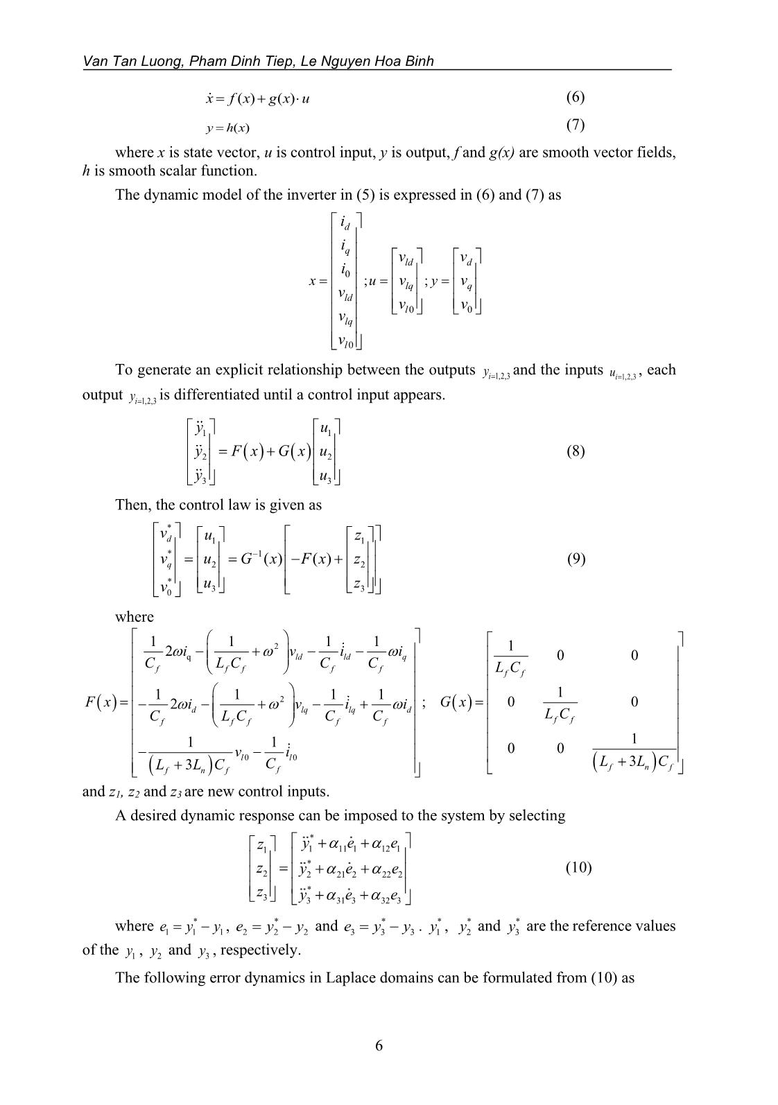
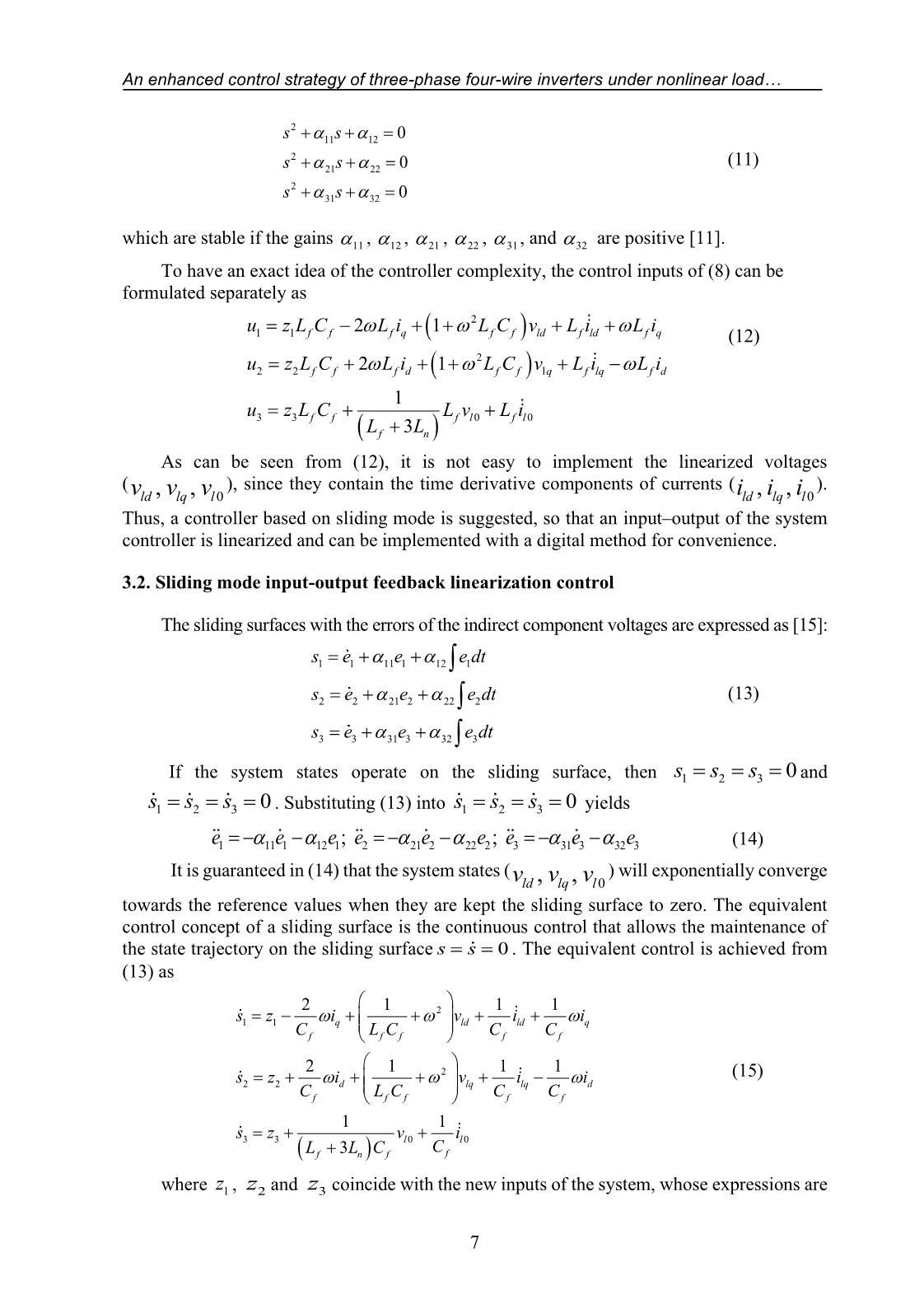
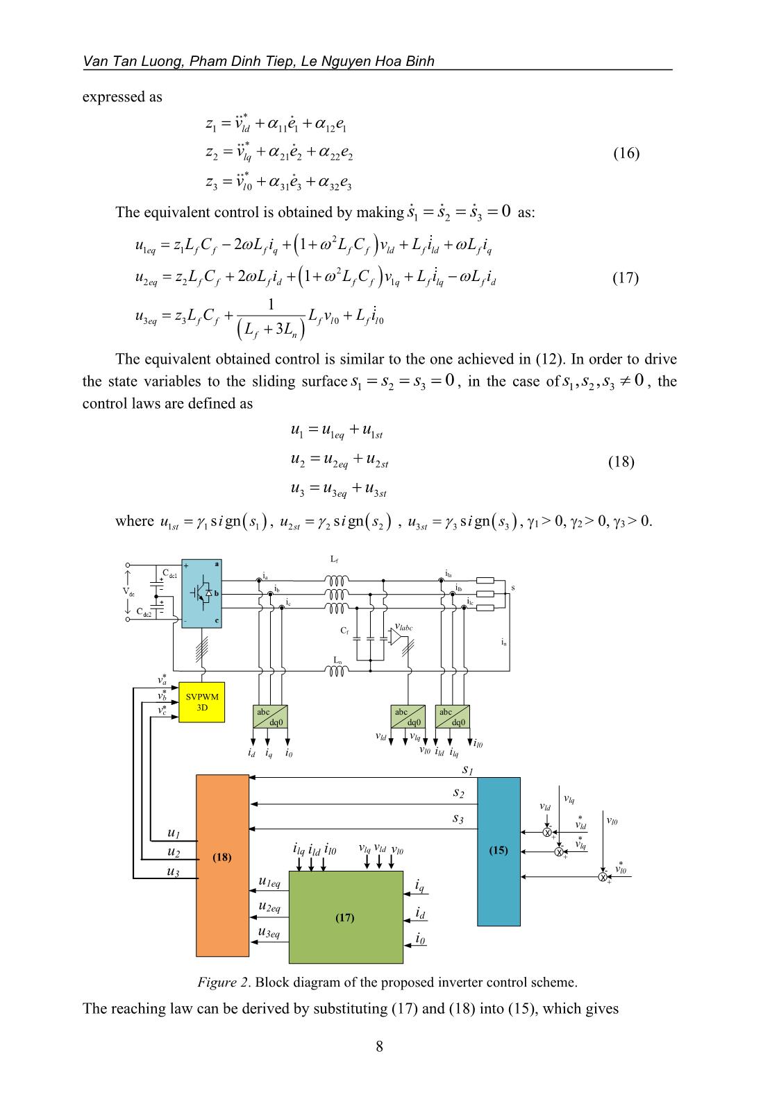
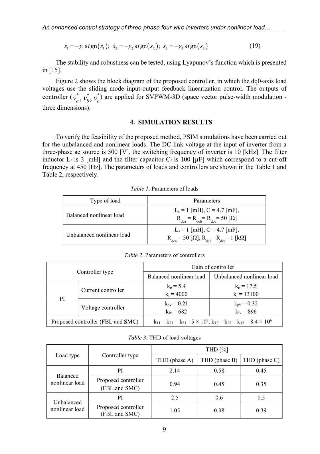
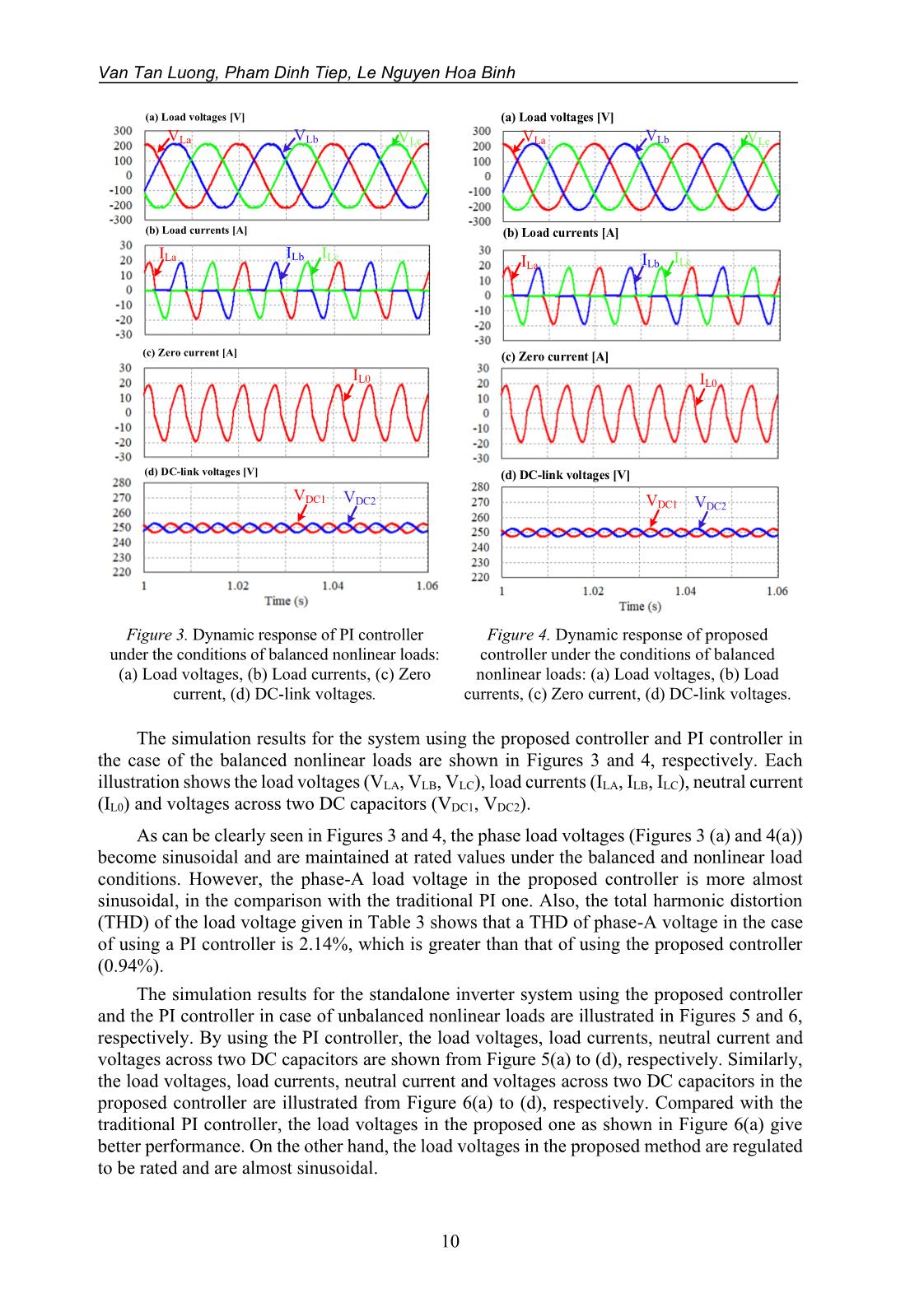
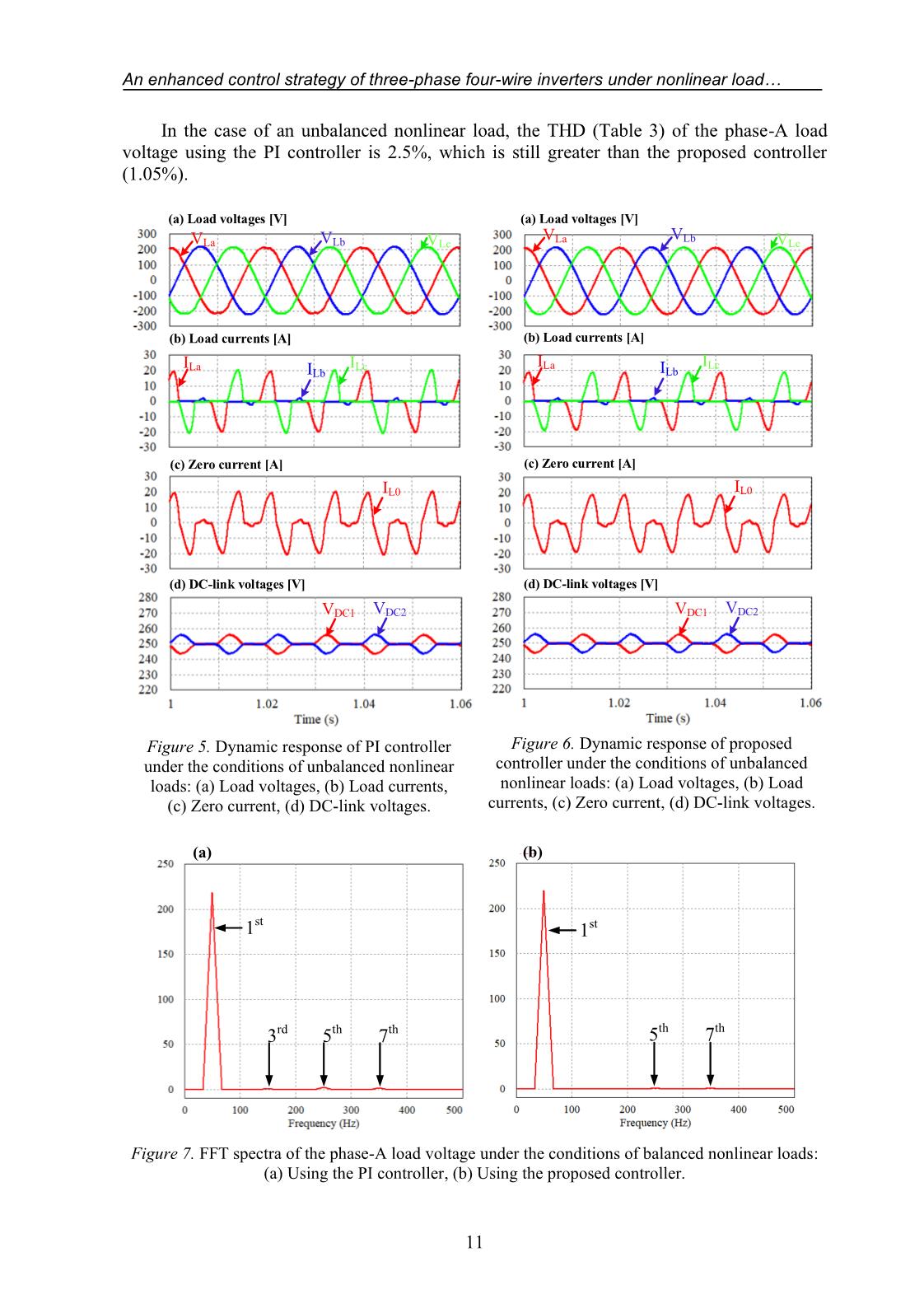
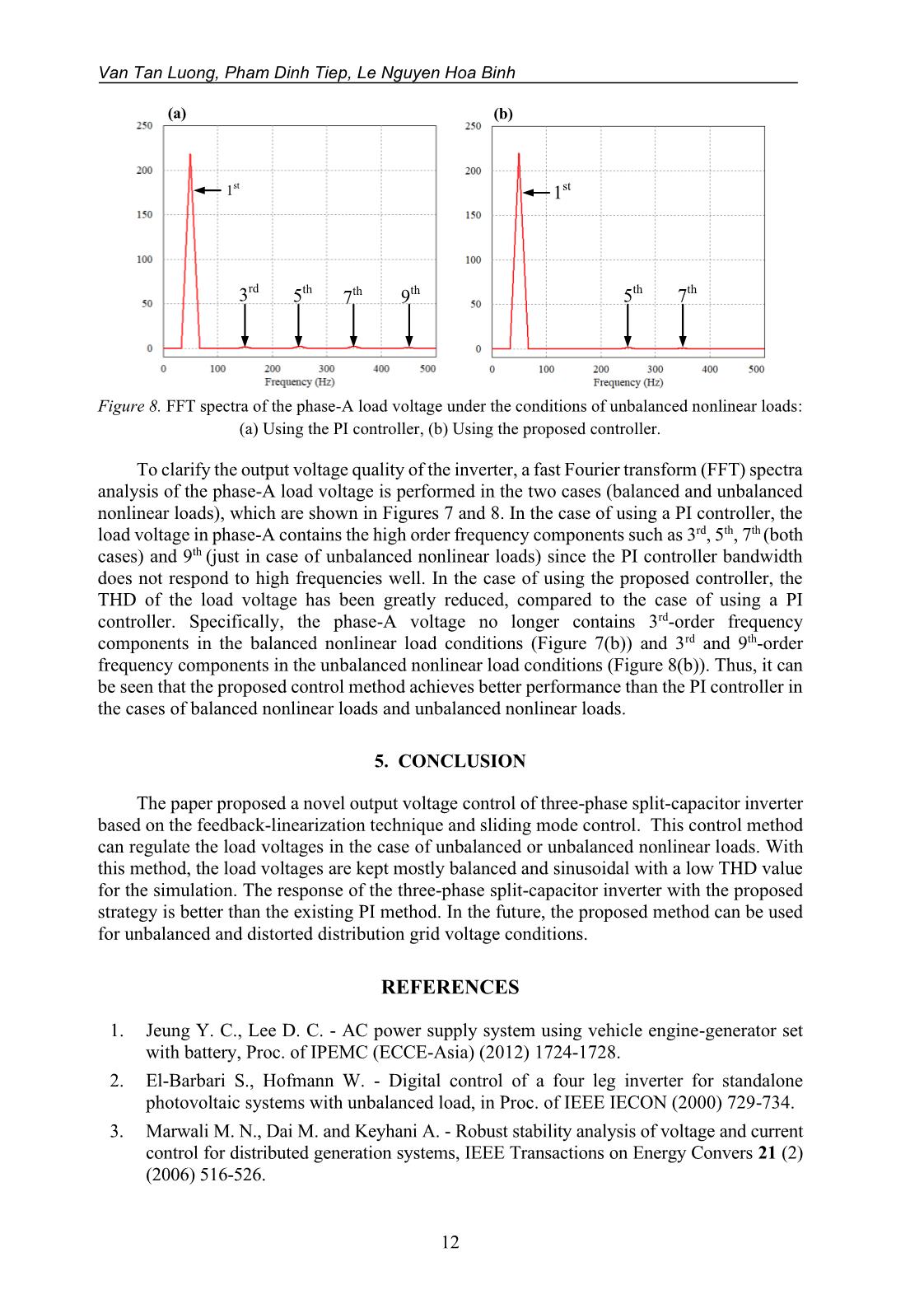
Journal of Science Technology and Food 21 (1) (2021) 3-14 AN ENHANCED CONTROL STRATEGY OF THREE-PHASE FOUR-WIRE INVERTERS UNDER NONLINEAR LOAD CONDITIONS Van Tan Luong1*, Pham Dinh Tiep1, Le Nguyen Hoa Binh2 1Ho Chi Minh City University of Food Industry 2Van Lang University *Email: luongvt@hufi.edu.vn Received: 19 January 2021; Accepted: 05 March 2021 ABSTRACT An enhanced nonlinear control technique based on a coordination between feedback linearization (FBL) approach and sliding mode control (SMC) is proposed for a three-phase split-capacitor inverter under the nonlinear load conditions. A nonlinear model of system with pulse-width modulation (PWM) voltage-source inverter (VSI) including the output inductor- capacitor (LC) filters is derived in the d-q-0 synchronous reference frame, not by small signal analysis. The controllers for d-q-0 components of three-phase line-to-neutral load voltages are designed by linear control theory. With the proposed coordination scheme, three-phase split-capacitor inverter provides an excellent control performance for regulating the load voltages with nearly zero steady-state errors in both the transient and steady states. The proposed scheme is verified by the simulation results which show that three-phase split-capacitor inverter gives a low total harmonic distortion (THD) for the load voltages under the balanced or unbalanced nonlinear load conditions. Keywords: Nonlinear load, three-phase inverter, feedback linearization, sliding mode control, unbalanced load. 1. INTRODUCTION Recently, three-phase inverter has been widely applied for standalone applications. These applications considered as loads could be the vehicles, trucks, or the photovoltaic power systems, and so on [1, 2]. These loads could be the three-phase loads and/or single-phase loads which can cause a three-phase unbalanced load, an irregularly distributed single-phase load or a balanced three-phase load operating at a fault condition. If the imbalanced loads appear in the system, the components of the unwanted negative-and zero-sequence currents are produced. The negative-sequence component of the currents can cause the excessive heating in machines, saturation of transformers and ripple in rectifiers. Meanwhile the zero-sequence currents cause excessive power losses in neutral lines and affect protection. The three-phase inverter is connected to a load by a four-wire system, in which the neutral point of both source and load sides is also grounded. Several different methods have been applied to provide the neutral point of the source side. In the one way, the / (delta/winding) transformer has been used, in which the and Y windings are connected to the inverter and the load, respectively [3]. For this, the zero-sequence current is trapped in the windings. However, the use of the transformer can make its topology bulky, heavy and costly. In the other ways, the three-phase split-capacitor inverters and the four-leg inverters equipped with 3 Van Tan Luong, Pham Dinh Tiep, Le Nguyen Hoa Binh the eight switches have been employed. Nevertheless, the two switches must be required to add to the four-leg inverters and the three-dimension space vector modulation is so complicated [4]. Fortunately, a three-phase three-leg inverter with split direct current (DC) bus is one topology which can implement the three-phase four-wire system with a neutral point, as seen in the connection point of the load in Figure 1. Compared to a three-phase three-wire system, this topology can cope with the zero-sequence to regulate the output voltages to be balanced and the zero-sequence current can flow in the connection between the neutral point and the mid-point of the capacitive divider. Several researches focusing on improving the quality of the output voltages for the inverters and uninterruptable power supply (UPS) have been suggested. A repetitive control is used to regulate the inverters for UPS applications, but this controller shows slow response and lack of systematical method to stabilize the dynamic error of the system [5, 6]. Although this method can obtain high performance of the output voltage, the techniques for the control design is relatively complicated. In [7], a control strategy applying the technique of the symmetrical sequence decomposition to extract the positive-, negative- and zero-sequence components from the unbalanced three-phase signals have been developed. The proportional- integral (PI) controllers for the current and voltage are used to regulate the output voltages of the inverter. However, the using of twelve PI controllers and the processes of the sequence decomposition and composition could increase the computation time. Also, this control strategy is only suitable for the case of unbalanced linear loads. Sliding-mode control techniques are applied for regulating ... , i lq i l0 Thus, a controller based on sliding mode is suggested, so that an input–output of the system controller is linearized and can be implemented with a digital method for convenience. 3.2. Sliding mode input-output feedback linearization control The sliding surfaces with the errors of the indirect component voltages are expressed as [15]: s= e + e + e dt 1 1 11 1 12 1 s= e + e + e dt (13) 2 2 21 2 22 2 s= e + e + e dt 3 3 31 3 32 3 If the system states operate on the sliding surface, then s1= s 2 = s 3 = 0 and s= s = s = 0 1 2 3 . Substituting (13) into yields e1= − 111 e − 121 e;; e 2 = − 212 e − 222 e e 3 = − 313 e − 323 e (14) It is guaranteed in (14) that the system states ( ) will exponentially converge towards the reference values when they are kept the sliding surface to zero. The equivalent control concept of a sliding surface is the continuous control that allows the maintenance of the state trajectory on the sliding surface ss==0 . The equivalent control is achieved from (13) as 2 1 1 1 s= z − i + + 2 v + i + i 11 q ld ld q CLCCCf f f f f 2 1 1 1 s= z + i + + 2 v + i − i (15) 22 d lq lq d CLCCCf f f f f 11 s3= z 3 + vll 0 + i 0 (LLCf+ 3 n) f C f where z1 , z2 and z3 coincide with the new inputs of the system, whose expressions are 7 Van Tan Luong, Pham Dinh Tiep, Le Nguyen Hoa Binh expressed as * z1= vld + 11 e 1 + 12 e 1 * z2= vlq + 21 e 2 + 22 e 2 (16) z= v* + e + e 3l 0 31 3 32 3 The equivalent control is obtained by making s1= s 2 = s 3 = 0 as: 2 u11eq= zLC f f −21 Li f q +( + LCvLi f f) ld + f ld + Li f q 2 u2eq= zLC 2 f f +21 Li f d +( + LCvLi f f) l q + f lq − Li f d (17) 1 u3eq= z 3 L f C f + L f v l 0 + L f i l 0 (LLfn+ 3 ) The equivalent obtained control is similar to the one achieved in (12). In order to drive the state variables to the sliding surface s1= s 2 = s 3 = 0 , in the case of s1, s 2 , s 3 0 , the control laws are defined as u1=+ u 1eq u 1 st u2=+ u 2eq u 2 st (18) u=+ u u 3 3eq 3 st where u1st = 1s i gn( s 1 ) , u2st = 2s i gn( s 2 ) , u3st = 3s i gn( s 3 ) , 1 > 0, 2 > 0, 3 > 0. Lf i ia la ib ilb s ic ilc vlabc Cf in Ln * va * vb SVPWM 3D v*c abc abc abc dq0 dq0 dq0 v v ld lq i v l0 id iq i0 l0 ild ilq s1 s2 vlq vld s3 * vl0 - vld u X 1 + * v - vlq ilq ild il0 vlq ld vl0 (15) X u2 (18) + * - vl0 u3 X u + 1eq iq u2eq (17) id u3eq i0 Figure 2. Block diagram of the proposed inverter control scheme. The reaching law can be derived by substituting (17) and (18) into (15), which gives 8 An enhanced control strategy of three-phase four-wire inverters under nonlinear load s= −sgn i s ; s = − sgn i s ; s = − sgn i s (19) 1 1( 1) 2 2( 2) 3 3( 3 ) The stability and robustness can be tested, using Lyapunov’s function which is presented in [15]. Figure 2 shows the block diagram of the proposed controller, in which the dq0-axis load voltages use the sliding mode input-output feedback linearization control. The outputs of controller ( ***) are applied for SVPWM-3D (space vector pulse-width modulation - va,, v b v c three dimensions). 4. SIMULATION RESULTS To verify the feasibility of the proposed method, PSIM simulations have been carried out for the unbalanced and nonlinear loads. The DC-link voltage at the input of inverter from a three-phase ac source is 500 [V], the switching frequency of inverter is 10 [kHz]. The filter inductor Lf is 3 [mH] and the filter capacitor Cf is 100 [µF] which correspond to a cut-off frequency at 450 [Hz]. The parameters of loads and controllers are shown in the Table 1 and Table 2, respectively. Table 1. Parameters of loads Type of load Parameters Ls = 1 [mH], C = 4.7 [mF], Balanced nonlinear load R = R = R = 50 [Ω] dca dcb dcc Ls = 1 [mH], C = 4.7 [mF], Unbalanced nonlinear load R = 50 [Ω], R = R = 1 [kΩ] dca dcb dcc Table 2. Parameters of controllers Gain of controller Controller type Balanced nonlinear load Unbalanced nonlinear load k = 5.4 k = 17.5 Current controller p p ki = 4000 ki = 13100 PI k = 0.21 k = 0.32 Voltage controller pv pv kiv = 682 kiv = 896 3 6 Proposed controller (FBL and SMC) k11 = k21 = k31= 5 × 10 , k12 = k22 = k32 = 8.4 × 10 Table 3. THD of load voltages THD [%] Load type Controller type THD (phase A) THD (phase B) THD (phase C) PI 2.14 0.58 0.45 Balanced Proposed controller nonlinear load 0.94 0.45 0.35 (FBL and SMC) PI 2.5 0.6 0.5 Unbalanced Proposed controller nonlinear load 1.05 0.38 0.39 (FBL and SMC) 9 Van Tan Luong, Pham Dinh Tiep, Le Nguyen Hoa Binh (a) Load voltages [V] (a) Load voltages [V] VLa VLb VLc VLa VLb VLc (b) Load currents [A] (b) Load currents [A] ILa ILb ILc ILa ILb ILc (c) Zero current [A] (c) Zero current [A] I L0 IL0 (d) DC-link voltages [V] (d) DC-link voltages [V] VDC1 V DC2 VDC1 VDC2 Figure 3. Dynamic response of PI controller Figure 4. Dynamic response of proposed under the conditions of balanced nonlinear loads: controller under the conditions of balanced (a) Load voltages, (b) Load currents, (c) Zero nonlinear loads: (a) Load voltages, (b) Load current, (d) DC-link voltages. currents, (c) Zero current, (d) DC-link voltages. The simulation results for the system using the proposed controller and PI controller in the case of the balanced nonlinear loads are shown in Figures 3 and 4, respectively. Each illustration shows the load voltages (VLA, VLB, VLC), load currents (ILA, ILB, ILC), neutral current (IL0) and voltages across two DC capacitors (VDC1, VDC2). As can be clearly seen in Figures 3 and 4, the phase load voltages (Figures 3 (a) and 4(a)) become sinusoidal and are maintained at rated values under the balanced and nonlinear load conditions. However, the phase-A load voltage in the proposed controller is more almost sinusoidal, in the comparison with the traditional PI one. Also, the total harmonic distortion (THD) of the load voltage given in Table 3 shows that a THD of phase-A voltage in the case of using a PI controller is 2.14%, which is greater than that of using the proposed controller (0.94%). The simulation results for the standalone inverter system using the proposed controller and the PI controller in case of unbalanced nonlinear loads are illustrated in Figures 5 and 6, respectively. By using the PI controller, the load voltages, load currents, neutral current and voltages across two DC capacitors are shown from Figure 5(a) to (d), respectively. Similarly, the load voltages, load currents, neutral current and voltages across two DC capacitors in the proposed controller are illustrated from Figure 6(a) to (d), respectively. Compared with the traditional PI controller, the load voltages in the proposed one as shown in Figure 6(a) give better performance. On the other hand, the load voltages in the proposed method are regulated to be rated and are almost sinusoidal. 10 An enhanced control strategy of three-phase four-wire inverters under nonlinear load In the case of an unbalanced nonlinear load, the THD (Table 3) of the phase-A load voltage using the PI controller is 2.5%, which is still greater than the proposed controller (1.05%). (a) Load voltages [V] (a) Load voltages [V] V V VLa VLb VLc La Lb VLc (b) Load currents [A] (b) Load currents [A] ILa ILc ILa ILc ILb ILb (c) Zero current [A] (c) Zero current [A] IL0 IL0 (d) DC-link voltages [V] (d) DC-link voltages [V] VDC1 VDC2 VDC1 VDC2 Figure 5. Dynamic response of PI controller Figure 6. Dynamic response of proposed under the conditions of unbalanced nonlinear controller under the conditions of unbalanced loads: (a) Load voltages, (b) Load currents, nonlinear loads: (a) Load voltages, (b) Load (c) Zero current, (d) DC-link voltages. currents, (c) Zero current, (d) DC-link voltages. (a) (b) 1st 1st 3rd 5th 7th 5th 7th Figure 7. FFT spectra of the phase-A load voltage under the conditions of balanced nonlinear loads: (a) Using the PI controller, (b) Using the proposed controller. 11 Van Tan Luong, Pham Dinh Tiep, Le Nguyen Hoa Binh (a) (b) 1st 1st 3rd 5th 7th 9th 5th 7th Figure 8. FFT spectra of the phase-A load voltage under the conditions of unbalanced nonlinear loads: (a) Using the PI controller, (b) Using the proposed controller. To clarify the output voltage quality of the inverter, a fast Fourier transform (FFT) spectra analysis of the phase-A load voltage is performed in the two cases (balanced and unbalanced nonlinear loads), which are shown in Figures 7 and 8. In the case of using a PI controller, the load voltage in phase-A contains the high order frequency components such as 3rd, 5th, 7th (both cases) and 9th (just in case of unbalanced nonlinear loads) since the PI controller bandwidth does not respond to high frequencies well. In the case of using the proposed controller, the THD of the load voltage has been greatly reduced, compared to the case of using a PI controller. Specifically, the phase-A voltage no longer contains 3rd-order frequency components in the balanced nonlinear load conditions (Figure 7(b)) and 3rd and 9th-order frequency components in the unbalanced nonlinear load conditions (Figure 8(b)). Thus, it can be seen that the proposed control method achieves better performance than the PI controller in the cases of balanced nonlinear loads and unbalanced nonlinear loads. 5. CONCLUSION The paper proposed a novel output voltage control of three-phase split-capacitor inverter based on the feedback-linearization technique and sliding mode control. This control method can regulate the load voltages in the case of unbalanced or unbalanced nonlinear loads. With this method, the load voltages are kept mostly balanced and sinusoidal with a low THD value for the simulation. The response of the three-phase split-capacitor inverter with the proposed strategy is better than the existing PI method. In the future, the proposed method can be used for unbalanced and distorted distribution grid voltage conditions. REFERENCES 1. Jeung Y. C., Lee D. C. - AC power supply system using vehicle engine-generator set with battery, Proc. of IPEMC (ECCE-Asia) (2012) 1724-1728. 2. El-Barbari S., Hofmann W. - Digital control of a four leg inverter for standalone photovoltaic systems with unbalanced load, in Proc. of IEEE IECON (2000) 729-734. 3. Marwali M. N., Dai M. and Keyhani A. - Robust stability analysis of voltage and current control for distributed generation systems, IEEE Transactions on Energy Convers 21 (2) (2006) 516-526. 12 An enhanced control strategy of three-phase four-wire inverters under nonlinear load 4. Zhang R., Prasad H., Boroyevich D., and Lee F. C. - Three-dimensional space vector modulation for four-leg voltage-source converters, IEEE Transactions on Power Electronics 17 (3) (2002) 314-326. 5. Haneyoshi T., Kawamura A. and Hoft R. G. - Waveform compensation of PWM inverter with cyclic fluctuating loads, IEEE Transactions on Industry Application 24 (4) (1988) 582-589. 6. Tzou Y. Y., Ou R. S., Jung S. L. and Chang M. Y. - High-performance programmable AC power source with low harmonic distortion using DSP-based repetitive control technique, IEEE Transactions on Power Electronics 12 (4) (1997) 715-725. 7. Mohd A., Ortjohann E., Hamsic N., Sinsukthavorn W., Lingemann M., Schmelter A., and Morton D. - Control strategy and space vector modulation for three-leg four-wire voltage source inverters under unbalanced load conditions, IET Power Electronics 3 (3) (2010) 323-333. 8. Zhang R., Boroyevich D., Prasad V. H., Mao H., Lee F. C., and Dubovsky S. - A three- phase inverter with a neutral leg with space vector modulation, in Proceedings of IEEE Applied Power Electronics Conference 2 (1997) 857-863. 9. Jung S. L. and Tzou Y. Y. - Discrete sliding-mode control of a PWM inverter for sinusoidal output waveform synthesis with optimal sliding curve, IEEE Transactions on Power Electronics 11 (4) (1996) 567-577. 10. Karimi H., Davison E. J., and Iravani R. - Multivariable servomechanism controller for autonomous operation of a distributed generation unit: Design and performance evaluation, IEEE Transactions on Power Systems 25 (2) (2010) 835-865. 11. Kim D-E, Lee D-C.- Feedback linearization control of three-phase UPS inverter system, IEEE Transactions on Industrial Electronics 57 (3) (2010) 963-968. 12. Vo N.Q.T., Lee D-C. - Advanced control of three-phase four-wire inverters using feedback linearization under unbalanced and nonlinear load condition, Transactions on Korean Institute of Power Electronics 18 (4) (2013) 333-341. 13. Jeong S.Y., Nguyen T.H., Le Q.A., Lee D.-C. - High-performance control of three-phase four-wire DVR systems using feedback linearization, Journal of Power Electronics 16 (1) (2016) 351-361. 14. Hosani K. A., Nguyen T. H., Sayari N. A. - An improved control strategy of 3P4W DVR systems under unbalanced and distorted voltage conditions, Electrical Power and Energy Systems 98 (2018) 233-242. 15. Slotine J.-J. E. and Li W.- Applied nonlinear control, Englewood Cliffs, NJ: Prentice- Hall (1991) 207-271. 13 Van Tan Luong, Pham Dinh Tiep, Le Nguyen Hoa Binh TÓM TẮT CHIẾN LƯỢC ĐIỀU KHIỂN NÂNG CAO CỦA BỘ NGHỊCH LƯU BA PHA BỐN DÂY TRONG TRƯỜNG HỢP TẢI PHI TUYẾN Văn Tấn Lượng1*, Phạm Đình Tiệp1, Lê Nguyễn Hòa Bình2 1Trường Đại học Công nghiệp Thực phẩm TP.HCM 2Trường Đại học Văn Lang *Email: luongvt@hufi.edu.vn Kỹ thuật điều khiển phi tuyến nâng cao dựa trên sự phối hợp giữa kỹ thuật tuyến tính hóa hồi tiếp (FBL) và điều khiển trượt (SMC) được đề xuất cho bộ nghịch lưu chia tụ ba pha trong trường hợp tải phi tuyến. Mô hình phi tuyến của hệ thống với bộ nghịch lưu nguồn điện áp điều chế độ rộng xung (PWM) bao gồm các bộ lọc LC ở ngõ ra được hình thành trong hệ tọa độ quay (dq0), mà không cần dùng phương pháp phân tích tín hiệu nhỏ. Bộ điều khiển đối với các thành phần d-q-0 của điện áp pha của tải được thiết kế theo kỹ thuật điều khiển tuyến tính. Với chiến lược kết hợp đề xuất, bộ nghịch lưu chia tụ ba pha tạo ra vận hành điều khiển tốt để điều khiển điện áp tải với sai số gần như bằng không cả trạng thái quá độ và xác lập. Chiến lược đề xuất được kiểm chứng bởi các kết quả mô phỏng, cho thấy rằng bộ nghịch lưu chia tụ ba pha cho độ méo hài tổng (THD) thấp đối với điện áp tải trong trường hợp tải phi tuyến cân bằng và không cân bằng. Từ khóa: Tải phi tuyến, bộ nghịch lưu ba pha, tuyến tính hóa hồi tiếp, điều khiển trượt, tải không cân bằng. 14
File đính kèm:
 an_enhanced_control_strategy_of_three_phase_four_wire_invert.pdf

