A moving element method using timoshenko’s beam theory for dynamic analysis of train - Track systems
Moving-load dymanic problems
which are very common in engineering
have received a lot of interests from
researchers all around the world from quite
early. It was believed that in 1847, the
collapse of Stephanson’s Bridge in
England motivated researchers to find out
accurately the effects of moving loads to
structures [1]. Among a large number of
structures subjected to moving load,
transport engineering structures like
railways, bridges or pavements have
gained much concern from beginning stage
[2].
Up to now many models have been developed to study the behavior of the transport structures
Kirchhoff’s plate theory. Moving loads
have also been split into many cases such
as moving constant or time depended
forces, moving masses and moving vehicle
systems. Besides that, to reflect the reality,
the effect of foundation on which the
structures lie has been counted and divided
into many cases like elastic and
viscoelastic foundations.
Trang 1
Trang 2
Trang 3
Trang 4
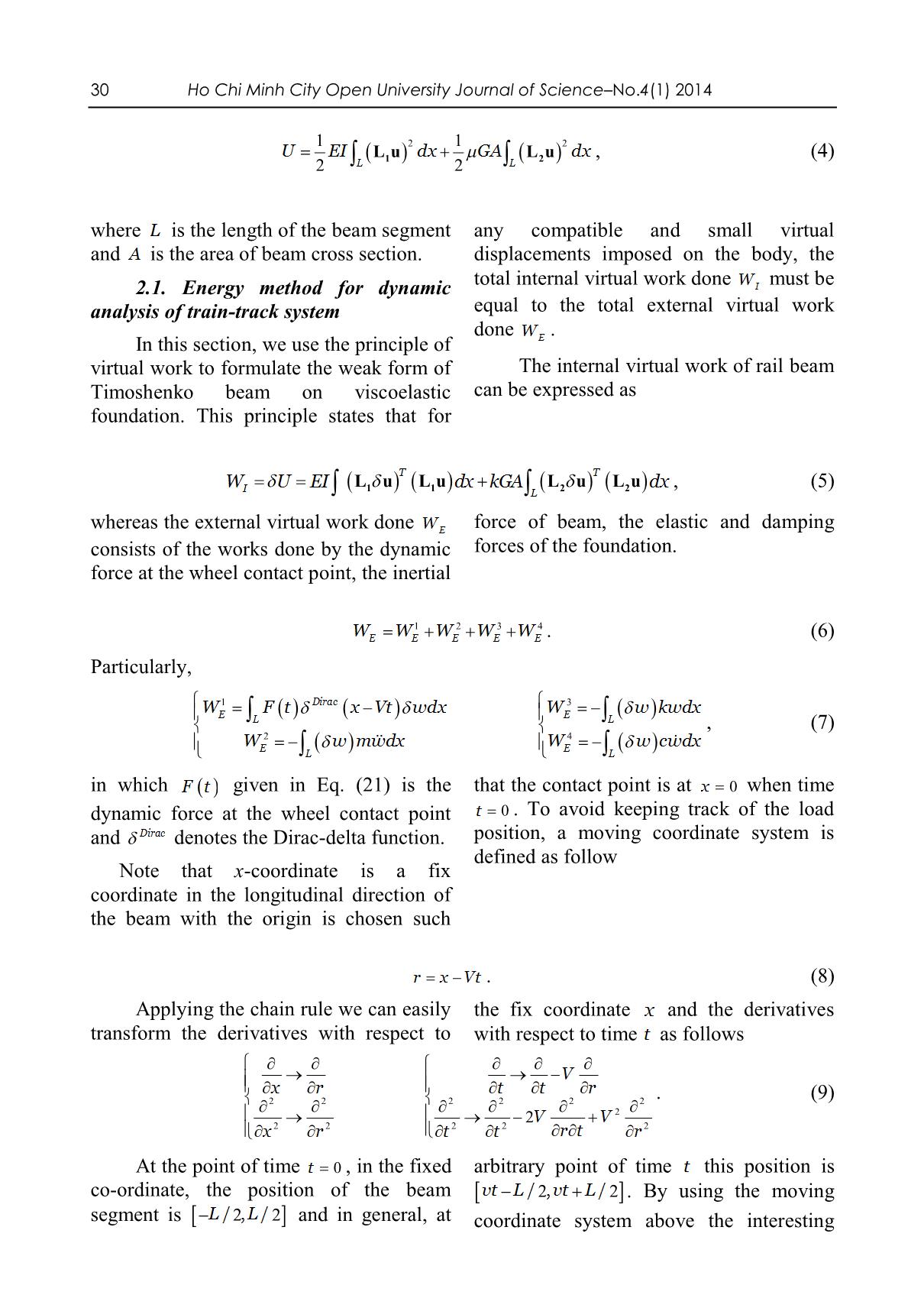
Trang 5
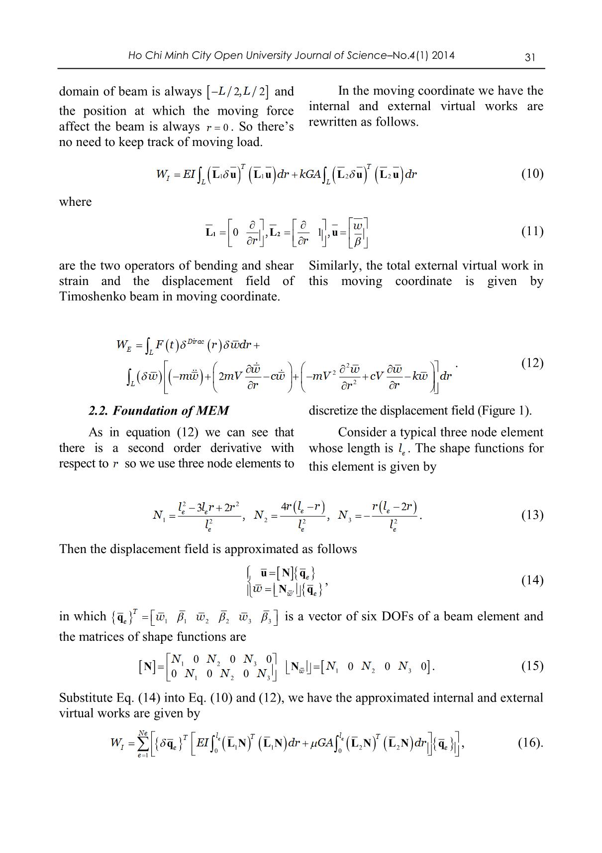
Trang 6
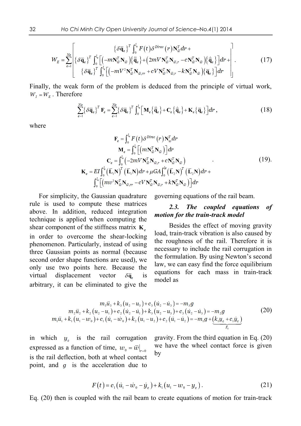
Trang 7
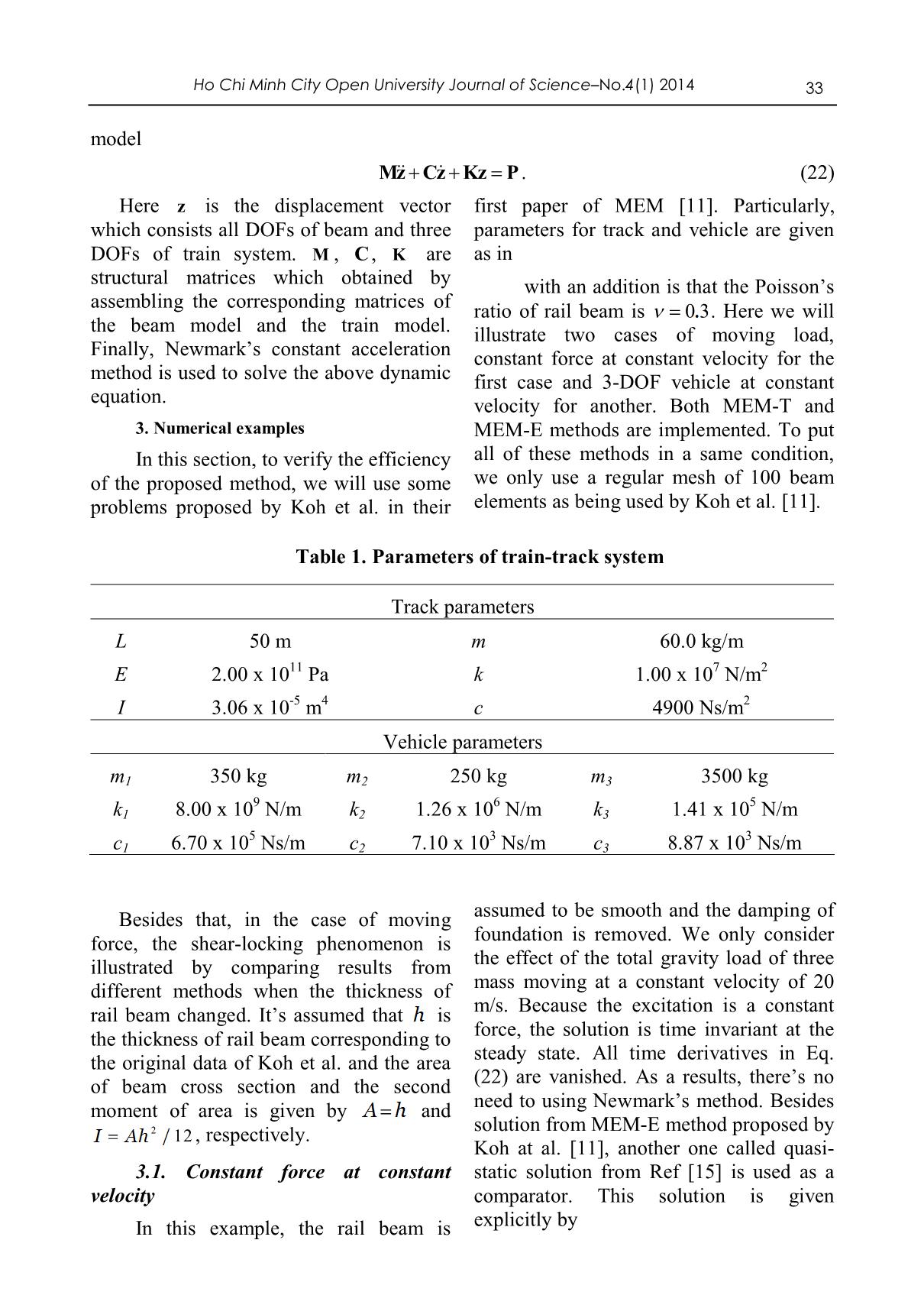
Trang 8
Trang 9
Trang 10
Tải về để xem bản đầy đủ
Tóm tắt nội dung tài liệu: A moving element method using timoshenko’s beam theory for dynamic analysis of train - Track systems
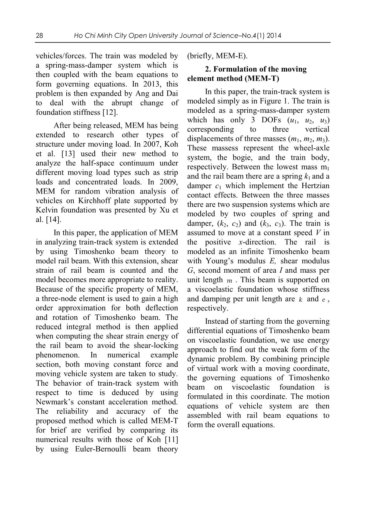
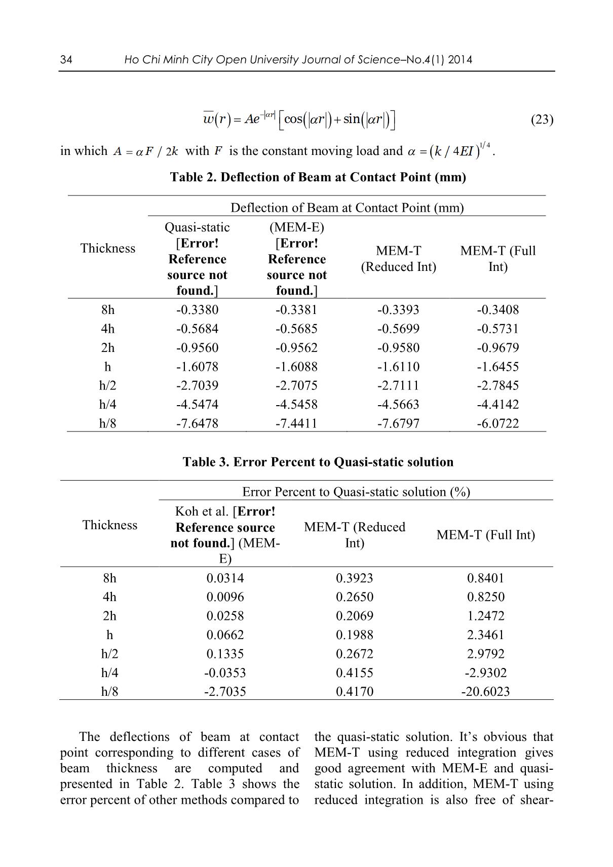
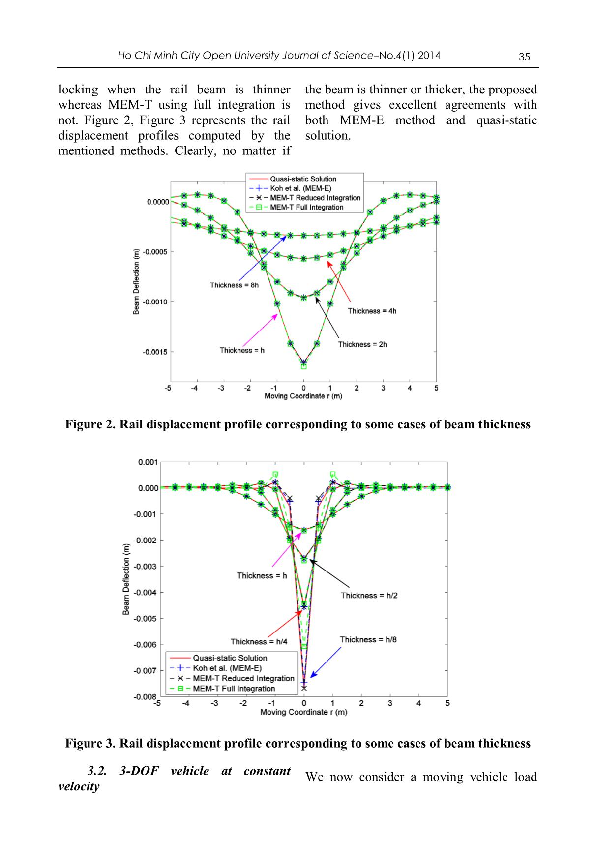
26 Ho Chi Minh City Open University Journal of Science–No.4(1) 2014 A MOVING ELEMENT METHOD USING TIMOSHENKO’S BEAM THEORY FOR DYNAMIC ANALYSIS OF TRAIN-TRACK SYSTEMS Nguyen Minh Nhan1, Nguyen Thoi Trung1,2, Nguyen Van Thanh3, Luong Van Hai3, Bui Xuan Thang22 1Division of Computational Mathematics and Engineering (CME), Institute for Computational Science (INCOS), Ton Duc Thang University, Viet Nam 2Department of Mechanics, Faculty of Mathematics & Computer Science, VNU-HCM University of Science, Viet Nam 3Faculty of Civil Engineering, VNU-HCM University of Technology, Viet Nam (Received: 23/02/2014; Revised: 02/04/2014; Accepted: 16/06/2014) ABSTRACT The paper presents a dynamic analysis of train-track systems supported by viscoelastic foundations by combining Timoshenko’s beam theory and moving element method (MEM). In the proposed method, a three-node beam element is utilized to get a high order approximation for the deflection of Timoshenko beam. The reduced integral method is applied in order to avoid the shear-locking phenomenon when computing the shear strain energy of the rail beam. In addition, the behavior of train-track system with respect to time is deduced by using Newmark’s constant acceleration method. Numerical results show that the proposed method is free of shear locking and gives a good agreement with Koh et al.’s method using Euler-Bernoulli beam theory. Keywords: train-track system, moving element method (MEM), Timoshenko beam theory, three node beam element, shear-locking phenomenon. 2 Correspondence to: Bui Xuan Thang, Faculty of Mathematics and Computer Science, University of Science, Vietnam National University – HCMC, 227 Nguyen Van Cu, District 5, Hochiminh city, Vietnam. E-mail address: bxthang@hcmus.edu.vn ; bxthang071@yahoo.com.vn Ho Chi Minh City Open University Journal of Science–No. 4(1) 2014 27 1. Introduction development of digital computers, many Moving-load dymanic problems numerical methods such as finite element which are very common in engineering method (FEM), mesh-free method, finite have received a lot of interests from difference method have been proposed. researchers all around the world from quite These new methods have made the early. It was believed that in 1847, the researching of mechanics in general and of collapse of Stephanson’s Bridge in moving load problems in particular England motivated researchers to find out become more convenient and expandable. accurately the effects of moving loads to Along with this, all branches of transport structures [1]. Among a large number of have obtained many great advances with structures subjected to moving load, huge increase in speed and weight of transport engineering structures like vehicles. This fact has made the railways, bridges or pavements have researching of dynamic responses of gained much concern from beginning stage structures under moving vehicles become [2]. more and more important. Although proving the strength in analyzing various Up to now many models have been developedstructures to study in engineering,the behavior of finite the transport element structures under moving loads. In these models, structural components which are usually considered as beams, plates or shells are idealized by some structural theories such as Euler Kirchhoff’s plate theory. Moving loads method (FEM) [8] has encountered many have also been split into many cases such obstacles when facing with moving load as moving constant or time depended problems. For example, a very large forces, moving masses and moving vehicle domain of structure subjected to high speed systems. Besides that, to reflect the reality, moving load requires a mesh with a lot of the effect of foundation on which the degrees of freedom (DOFs). Besides that, structures lie has been counted and divided keeping track of load positions related to into many cases like elastic and mesh nodes is unavoidable. These viscoelastic foundations. restrictions have increased much Initially, analytic methods have been computational cost. Therefore, recently, to used widely to study the effect of moving solve this kind of problems, some new load to transport structures. Some of these approaches which commonly use moving methods which can be named here are the coordinates have appeared and improved method of using Green’s function and their efficiency. integral equations [3], method of expansion In 2000 and 2001, Chen and Huang of the eigen-functions [4], Galerkin’s [9, 10] studied infinite Timoshenko beam method [5] and the Fourier transform subjected to a moving load on viscoelastic method (FTM) [6, 7]. For example, in 1958 foundation. By using a moving coordinate and 1959, P. M. Mathews [6, 7] made an as Matthew [6, 7], the dynamic stiffness analysis of vibration of an infinite uniform matrix of the beam with the velocity beam on e ... x Then the strain and stress fields are easily deduced as z E Ez x x x x x , (2) w w xz xz GG xz x x where is the shear coefficient which is usually given by 5/ 6 . If we set two operators of bending and shear strain and the displacement field of Timoshenko beam which contains only the deflection w and rotation as w L 0,, L 1 u 1 2 , (3) x x then the energy strain of Timoshenko beam which is a sum of bending and shear component is written briefly as 30 Ho Chi Minh City Open University Journal of Science–No.4(1) 2014 12 1 2 U EI L u dx GA L u dx , (4) 2 LL1 2 2 where L is the length of the beam segment any compatible and small virtual and A is the area of beam cross section. displacements imposed on the body, the total internal virtual work done W must be 2.1. Energy method for dynamic I analysis of train-track system equal to the total external virtual work done W . In this section, we use the principle of E virtual work to formulate the weak form of The internal virtual work of rail beam Timoshenko beam on viscoelastic can be expressed as foundation. This principle states that for W U EI L u TT L u dx kGA L u L u dx , (5) I 1 1 L 2 2 whereas the external virtual work done W E force of beam, the elastic and damping consists of the works done by the dynamic forces of the foundation. force at the wheel contact point, the inertial WWWWW 1 2 3 4 . (6) EEEEE Particularly, W1 F t Dirac x Vt wdx W3 w kwdx E L E L , (7) W2 w mwdx W4 w cwdx E L E L in which F t given in Eq. (21) is the that the contact point is at x 0 when time dynamic force at the wheel contact point t 0 . To avoid keeping track of the load and Dirac denotes the Dirac-delta function. position, a moving coordinate system is defined as follow Note that x-coordinate is a fix coordinate in the longitudinal direction of the beam with the origin is chosen such r x Vt . (8) Applying the chain rule we can easily the fix coordinate x and the derivatives transform the derivatives with respect to with respect to time t as follows V x r t t r . (9) 2 2 2 2 2 2 2VV 2 2 2 2 2 2 x r t t r t r At the point of time t 0 , in the fixed arbitrary point of time t this position is co-ordinate, the position of the beam vt L/,/2 vt L 2 . By using the moving segment is LL/,/2 2 and in general, at coordinate system above the interesting Ho Chi Minh City Open University Journal of Science–No. 4(1) 2014 31 domain of beam is always LL/,/2 2 and In the moving coordinate we have the the position at which the moving force internal and external virtual works are affect the beam is always r 0 . So there’s rewritten as follows. no need to keep track of moving load. T T WI EI L1 u L 1 u dr kGA L 2 u L 2 u dr (10) L L where w L1 0 ,, L 2 1 u (11) r r are the two operators of bending and shear Similarly, the total external virtual work in strain and the displacement field of this moving coordinate is given by Timoshenko beam in moving coordinate. W F t Dirac r wdr E L w 2 w w . (12) w mw 2mV cw mV2 cV kw dr L 2 r r r 2.2. Foundation of MEM discretize the displacement field (Figure 1). As in equation (12) we can see that Consider a typical three node element there is a second order derivative with whose length is le . The shape functions for respect to r so we use three node elements to this element is given by l2 3 l r 2 r 2 4r l r r l 2 r N e e ,,NN e e . (13) 1 l 2 2l 2 3 l2 e e e Then the displacement field is approximated as follows u N qe , (14) w N q w e T in which qe w1 1 w 2 2 w 3 3 is a vector of six DOFs of a beam element and the matrices of shape functions are NNN0 0 0 NN 1 2 3 NNN0 0 0 . (15) 0NNN 0 0 w 1 2 3 1 2 3 Substitute Eq. (14) into Eq. (10) and (12), we have the approximated internal and external virtual works are given by Ne l l T eTT e WI q e EI L1 N L 1 N dr GA L 2 N L 2 N dr q e , (16). 0 0 e 1 32 Ho Chi Minh City Open University Journal of Science–No.4(1) 2014 l qT e F t Dirac r N T dr e 0 w Ne l W qT e m NT N q 2 mV NT N c NT N q dr . (17) E e 0 wwe wwrwwe, e 1 l qT e mV2 NT N cV NT N k NT N q dr e 0 wwrr, wwr, wwe Finally, the weak form of the problem is deduced from the principle of virtual work, WWIE . Therefore Ne Ne l qT F qT e M q C q K q dr , (18) e e e 0 e e e e e e e 1 e 1 where l F e F t Dirac r N T dr e 0 w l MNN e mT dr e 0 w w l C e 2mV NNT cNNT . (19). e 0 w w, r w w lTT le KLNLNLNLN EIe dr GA dr e 0 1 1 0 2 2 l e 2 T T T mvNNNNNNw w,, rr cVw w r kw w dr 0 For simplicity, the Gaussian quadrature governing equations of the rail beam. rule is used to compute these matrices 2.3. The coupled equations of above. In addition, reduced integration motion for the train-track model technique is applied when computing the Besides the effect of moving gravity shear component of the stiffness matrix K e in order to overcome the shear-locking load, train-track vibration is also caused by phenomenon. Particularly, instead of using the roughness of the rail. Therefore it is three Gaussian points as normal (because necessary to include the rail corrugation in second order shape functions are used), we the formulation. By using Newton’s second only use two points here. Because the law, we can easy find the force equilibrium equations for each mass in train-track virtual displacement vector q is e model as arbitrary, it can be eliminated to give the m3 u 3 k 3 u 2 u 3 c 3 u 2 u 3 m 3 g mukuu22221221 cuu kuu 323323 cuu mg 2 (20) mukuw cuw kuu cuu mgkycy 11110110212212 1 1c 1 c Fc in which yc is the rail corrugation gravity. From the third equation in Eq. (20) expressed as a function of time, w w we have the wheel contact force is given 0 r 0 by is the rail deflection, both at wheel contact point, and g is the acceleration due to F t c u w y k u w y . (21) 1 1 0c 1 1 0 c Eq. (20) then is coupled with the rail beam to create equations of motion for train-track Ho Chi Minh City Open University Journal of Science–No. 4(1) 2014 33 model Mz Cz Kz P. (22) Here z is the displacement vector first paper of MEM [11]. Particularly, which consists all DOFs of beam and three parameters for track and vehicle are given DOFs of train system. M , C, K are as in structural matrices which obtained by with an addition is that the Poisson’s assembling the corresponding matrices of ratio of rail beam is 0. 3. Here we will the beam model and the train model. illustrate two cases of moving load, Finally, Newmark’s constant acceleration constant force at constant velocity for the method is used to solve the above dynamic first case and 3-DOF vehicle at constant equation. velocity for another. Both MEM-T and 3. Numerical examples MEM-E methods are implemented. To put In this section, to verify the efficiency all of these methods in a same condition, of the proposed method, we will use some we only use a regular mesh of 100 beam problems proposed by Koh et al. in their elements as being used by Koh et al. [11]. Table 1. Parameters of train-track system Track parameters L 50 m m 60.0 kg/m E 2.00 x 10¹¹ Pa k 1.00 x 10⁷ N/m2 I 3.06 x 10⁻⁵ m4 c 4900 Ns/m2 Vehicle parameters m1 350 kg m2 250 kg m3 3500 kg 9 6 5 k1 8.00 x 10 N/m k2 1.26 x 10 N/m k3 1.41 x 10 N/m 5 3 3 c1 6.70 x 10 Ns/m c2 7.10 x 10 Ns/m c3 8.87 x 10 Ns/m Besides that, in the case of moving assumed to be smooth and the damping of force, the shear-locking phenomenon is foundation is removed. We only consider illustrated by comparing results from the effect of the total gravity load of three different methods when the thickness of mass moving at a constant velocity of 20 rail beam changed. It’s assumed that h is m/s. Because the excitation is a constant the thickness of rail beam corresponding to force, the solution is time invariant at the the original data of Koh et al. and the area steady state. All time derivatives in Eq. of beam cross section and the second (22) are vanished. As a results, there’s no moment of area is given by A h and need to using Newmark’s method. Besides solution from MEM-E method proposed by I Ah 2 /12 , respectively. Koh at al. [11], another one called quasi- 3.1. Constant force at constant static solution from Ref [15] is used as a velocity comparator. This solution is given In this example, the rail beam is explicitly by 34 Ho Chi Minh City Open University Journal of Science–No.4(1) 2014 w r Ae r cos r sin r (23) 1/ 4 in which A F/ 2 k with F is the constant moving load and k/ 4 EI . Table 2. Deflection of Beam at Contact Point (mm) Deflection of Beam at Contact Point (mm) Quasi-static (MEM-E) [Error! [Error! Thickness MEM-T MEM-T (Full Reference Reference (Reduced Int) Int) source not source not found.] found.] 8h -0.3380 -0.3381 -0.3393 -0.3408 4h -0.5684 -0.5685 -0.5699 -0.5731 2h -0.9560 -0.9562 -0.9580 -0.9679 h -1.6078 -1.6088 -1.6110 -1.6455 h/2 -2.7039 -2.7075 -2.7111 -2.7845 h/4 -4.5474 -4.5458 -4.5663 -4.4142 h/8 -7.6478 -7.4411 -7.6797 -6.0722 Table 3. Error Percent to Quasi-static solution Error Percent to Quasi-static solution (%) Koh et al. [Error! Thickness Reference source MEM-T (Reduced MEM-T (Full Int) not found.] (MEM- Int) E) 8h 0.0314 0.3923 0.8401 4h 0.0096 0.2650 0.8250 2h 0.0258 0.2069 1.2472 h 0.0662 0.1988 2.3461 h/2 0.1335 0.2672 2.9792 h/4 -0.0353 0.4155 -2.9302 h/8 -2.7035 0.4170 -20.6023 The deflections of beam at contact the quasi-static solution. It’s obvious that point corresponding to different cases of MEM-T using reduced integration gives beam thickness are computed and good agreement with MEM-E and quasi- presented in Table 2. Table 3 shows the static solution. In addition, MEM-T using error percent of other methods compared to reduced integration is also free of shear- Ho Chi Minh City Open University Journal of Science–No.4 (1) 2014 35 locking when the rail beam is thinner the beam is thinner or thicker, the proposed whereas MEM-T using full integration is method gives excellent agreements with not. Figure 2, Figure 3 represents the rail both MEM-E method and quasi-static displacement profiles computed by the solution. mentioned methods. Clearly, no matter if Figure 2. Rail displacement profile corresponding to some cases of beam thickness Figure 3. Rail displacement profile corresponding to some cases of beam thickness 3.2. 3-DOF vehicle at constant We now consider a moving vehicle load velocity 36 Ho Chi Minh City Open University Journal of Science–No.4(1) 2014 instead of a pure force. In this case, the rail is given by a periodic function, corrugation is counted as an excitation and y x ysin2 x / y sin 2 Vt / (24) c c0 c c 0 c where the amplitude and wavelength are The displacement of beam at wheel contact given by yc 0 0. 5 mm, c 0. 5 m, point and displacements of three masses respectively. The vehicle is modeled as a which represent three components of the spring-mass-damper moving on the rail train is taken to study. beam at a constant velocity, V 20 m/s. Figure 4. Displacements of train masses and displacement of beam at the contact point The dynamic equations of MEM is c / V = 0.025s. In these results, the static solved by using Newmark’s constant responses due to self-weight of the three acceleration with a time step of 0. 0001s and masses are excluded. We can see an at-rest initial conditions. As in previous excellent agreement between MEM-T using example, MEM-E and MEM-T with reduced integration and MEM-E proposed reduced or full integration used are by Koh et al. implemented. Figure 4 shows the dynamic 4. Conclusion responses of the rail displacement at the contact point and the displacements of three In this paper, the moving element masses in a typical corrugation cycle, T= method (MEM) is extended to analyze the dynamic behaviors of train-track system Ho Chi Minh City Open University Journal of Science–No. 4(1) 2014 37 which is modeled by a Timoshenko beam theory. The obtained results are very on viscoelastic foundation subjected to a promising to extend to analyze the moving spring-mass-damper system. The dynamic behavior of beam structures made proposed method is hence called as the by composite and FGM. MEM-T. The coupled train-track Acknowledgements governing equations are then established and solved by Newmark’s constant This work was supported by Vietnam acceleration. In the MEM-T, the reduced National Foundation for Science & integration is used to avoid the shear Technology Development (NAFOSTED), locking. The numerical examples show that Ministry of Science & Technology, under the results by the MEM-T agree well with the basic research program (Project No.: those by Koh et al. [11] using Euler beam 107.02-2012.05). REFERENCES Ang KK, Dai J. Response analysis of high-speed rail system accounting for abrupt change of foundation stiffness. Journal of Sound and Vibration. 2013;332(12):2954- 70. Bondar NG. Dynamic Calculations of Beams Subjected to a Moving Load. Issledovaniya po teorii sooruzhenii. 1954;6:11-23. Chen YH, Huang YH, Shih CT. Response of an infinite Timoshenko beam on a viscoelastic foundation to a harmonic moving load. Journal of Sound and Vibration. 2001;241(5):809-24. Chen YH, Huang YH. Dynamic stiffness of infinite Timoshenko beam on viscoelastic foundation in moving co-ordinate. International Journal for Numerical Methods in Engineering. 2000;48(1):1-18. Frýba L. Vibration of solids and structures under moving loads. 3rd ed. ed. Thomas Telford: London; 1999. Koh CG, Chiew GH, Lim CC. A numerical method for moving load on continuum. Journal of Sound and Vibration. 2007;300(1-2):126-38. Koh CG, Ong JSY, Chua DKH, Feng J. Moving element method for train-track dynamics. International Journal for Numerical Methods in Engineering. 2003;56(11):1549-67. Krylov AN. Mathematical collection of papers of the academy of sciences. Mathematische Annalen. 1905;61. Lou P, Zeng QY. Vertical vehicle-track coupling element. Proceedings of the Institution of Mechanical Engineers Part F-Journal of Rail and Rapid Transit. 2006;220(3):293- 304. Mathews PM. Vibrations of a beam on elastic foundation II. ZAMM - Journal of Applied
File đính kèm:
 a_moving_element_method_using_timoshenkos_beam_theory_for_dy.pdf

